Chamfer Meaning: Chamfer vs Bevel vs Fillet | KXT
CNC Machining & Engineering Guide
What Is a Chamfer? Chamfer vs Bevel vs Fillet Explained
What is the difference between a chamfer, a bevel, and a fillet? These terms describe ways to modify an edge, but they are not always interchangeable. Understanding the geometry, applications, and manufacturing requirements helps engineers design parts that are easier to assemble, safer to handle, and more practical to manufacture.
This guide explains the meaning of a chamfer, clarifies the difference between a chamfer and a bevel, compares both with fillets, and shows how these features are specified and produced in CNC machining.
Quick Answer
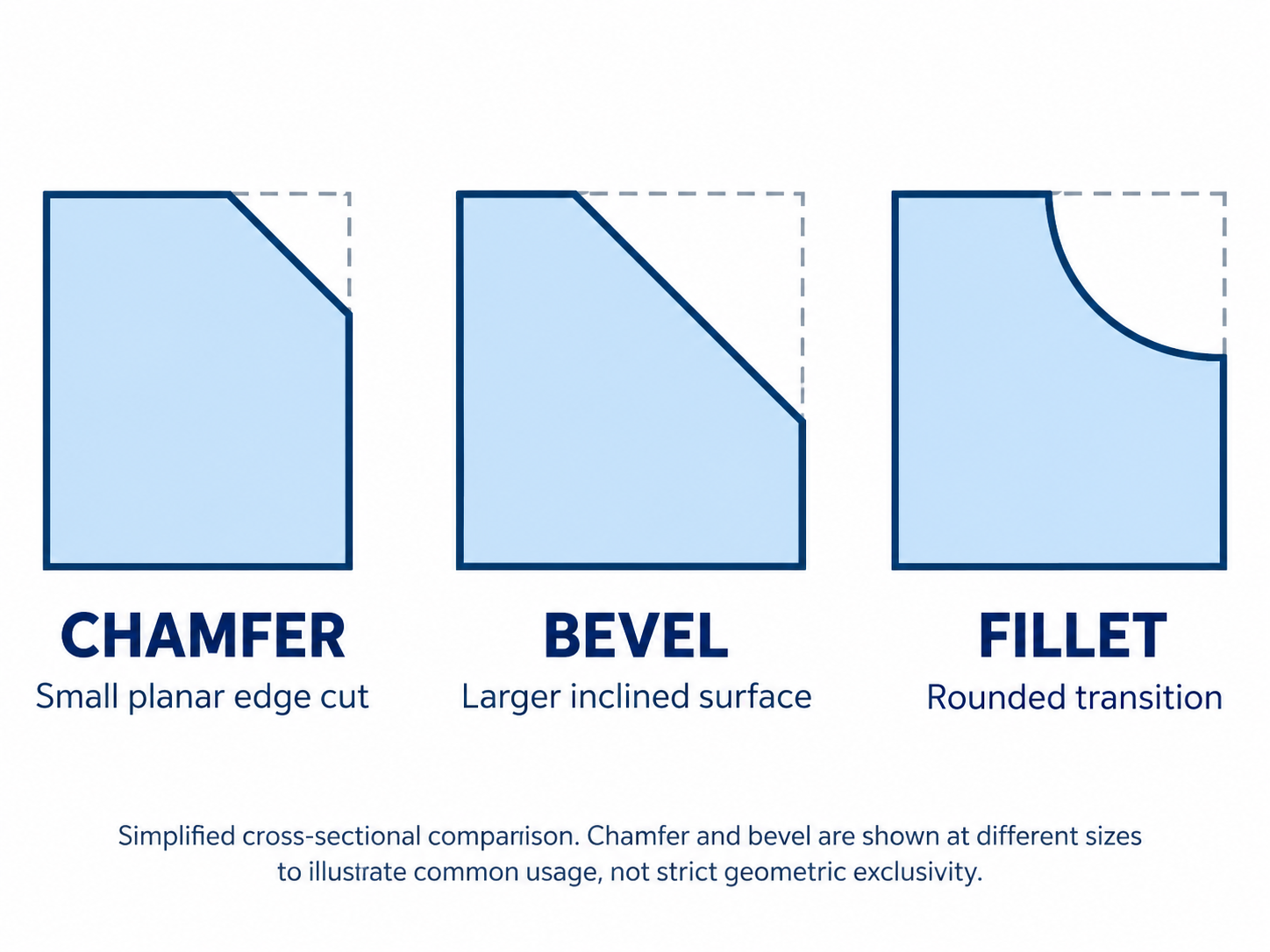
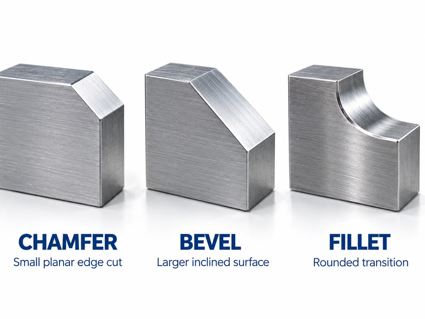
A chamfer is a flat, angled transition that replaces a sharp edge or corner. A bevel is an inclined edge or surface, often extending across a larger portion of a part. A fillet is a rounded transition between adjoining surfaces.
Chamfers and bevels can overlap in meaning: a chamfer is often considered a specific type of beveled edge. The exact terminology depends on the drawing, industry, and intended function. Unlike these planar features, a circular fillet uses a radius to define its curved profile.
1. What Is a Chamfer? Meaning and Purpose
In engineering and manufacturing, a chamfer is a flat, angled face that replaces the sharp intersection of two adjacent surfaces. In machined components, the chamfer is commonly produced by material removal; it can also be formed by other manufacturing processes.
Chamfers are widely used on machined metal components, plastic parts, holes, shafts, threaded features, and assembly interfaces. They can be produced by milling, turning, drilling-related operations, grinding, or other suitable manufacturing methods.
A 45-degree chamfer is common, especially where two perpendicular surfaces meet. However, a chamfer does not have to be 45 degrees. Its angle and dimensions should follow the engineering drawing and functional requirements.
What Is the Purpose of a Chamfer?
- Edge safety: Removing sharp corners can make components safer to handle.
- Assembly: An entry chamfer can help guide a shaft, pin, fastener, or mating component into position.
- Deburring: A controlled chamfering operation can remove burrs left by machining.
- Edge protection: Breaking a sharp edge may reduce the likelihood of small chips or damage during handling.
- Functional clearance: Chamfers can prevent interference at mating corners.
- Appearance: A consistent chamfer creates a deliberate, uniform edge finish.
Common Chamfer Applications
Precision Machined Parts
Chamfering removes sharp edges on milled or turned components and can create controlled assembly interfaces.
Hole Entrances
A chamfer around a hole may help guide a fastener or pin, remove drilling burrs, or provide a required entry geometry.
Shafts and Pins
Entry chamfers can improve alignment during assembly and reduce interference with mating components.
Mold Components
Controlled edge geometry can support assembly, maintenance, and protection of selected non-functional sharp edges.
2. Chamfer vs Bevel: What Is the Difference?
The difference between a bevel and a chamfer is primarily about how the terms are used to describe an inclined surface. Both can create a flat, sloping edge.
In many mechanical drawings, a chamfer refers to a relatively small, dimensioned edge modification. Bevel is a broader term for an inclined edge or surface and is frequently used in applications such as plate preparation, welded joints, and woodworking.
There is no universal geometric rule stating that a chamfer must be 45 degrees while a bevel must use another angle. Both can be made at different angles.
Chamfer vs Bevel Comparison Table
| Feature | Chamfer | Bevel |
|---|---|---|
| Basic meaning | Flat angled edge transition | Inclined edge or surface |
| Typical extent | Often a small edge feature | Can cover a larger edge region |
| Angle | Often 45°, but not limited to it | Depends on design requirements |
| Common purpose | Edge breaking, assembly, deburring | Joint preparation, clearance, edge design |
| Typical industries | CNC machining, precision engineering | Machining, fabrication, welding, woodworking |
| Are they interchangeable? | Sometimes in general language, but a manufacturing drawing should define the actual geometry. | |
Is a Chamfer the Same as a Bevel?
Sometimes, yes. A chamfered edge can also be described as beveled because it has an inclined flat surface.
However, the terms emphasize different things. Chamfer usually refers to a specific edge treatment, while bevel may describe a wider range of inclined geometries.
The most reliable way to distinguish a chamfer from a bevel is to examine the specified angle, location, dimensions, and intended function rather than relying on the name alone.
Chamfered vs Beveled: What Does It Mean?
Chamfered describes an edge that has received a chamfer. Beveled describes an edge or surface that has been cut or formed at an inclination.
In American English, beveled is the usual spelling. British English also commonly uses bevelled. Therefore, searches such as beveled vs chamfered and bevelled vs chamfered generally ask the same underlying question.
For CNC manufacturing, a drawing note specifying a 0.5 mm by 45° chamfer is more useful than a general instruction to make an edge beveled.
3. Chamfer vs Bevel vs Fillet: Side-by-Side Comparison
The three terms describe different edge treatments, but chamfer and bevel are closely related. The clearest geometric distinction is between a planar inclined transition and a rounded transition.
| Property | Chamfer | Bevel | Fillet |
|---|---|---|---|
| Edge geometry | Flat angled surface | Inclined surface | Curved transition |
| Typical specification | Size and angle | Angle and dimensions | Radius or defined profile |
| Typical function | Edge removal and assembly | Joint or surface preparation | Smooth geometric transition |
| Typical machining | Chamfer milling, turning | Angle milling, bevel machining | Radius milling, form machining |
| Important consideration | Chamfer size and angle | Slope, extent, and fit | Radius, clearance, and loading |
Chamfer vs Fillet: Which Is Better?
Neither is automatically better. A chamfer can be efficient for removing sharp edges and creating an assembly lead-in. A fillet can provide a smoother transition where a radius is required for geometry, flow, or stress management.
For example, a small chamfer at the entrance of a precision bore may help guide a mating pin. By contrast, a designed radius at a highly loaded internal corner may be preferable to a sharp intersection.
The required design should be evaluated against loading, available space, mating parts, machining access, and inspection requirements.
External Fillets and Internal Fillets
The word fillet is used for rounded transitions on both exterior and interior geometry. Depending on the application, an external rounded corner may also be called a round. In CAD modeling, the fillet command often creates a radius-based transition.
In manufacturing, the selected cutting tool must be able to produce the required surface without interfering with neighboring features.
4. Chamfer Dimensions and Engineering Drawing Examples
A chamfer should be defined by a drawing requirement rather than an assumed standard angle. The notation normally communicates the feature size and, when necessary, its angle or another controlling dimension.
What Does C0.5 Mean on a Drawing?
In many metric drawings using the C-chamfer convention, C0.5 denotes a nominal 45° chamfer with 0.5 mm setbacks along the two originally intersecting surfaces when those surfaces meet at 90°. This notation is not universal.
However, drawing notation depends on the applicable drafting standard, company convention, and general notes. Do not interpret an unfamiliar callout without confirming the drawing's dimensional rules.
What Does 0.5 × 45° Mean?
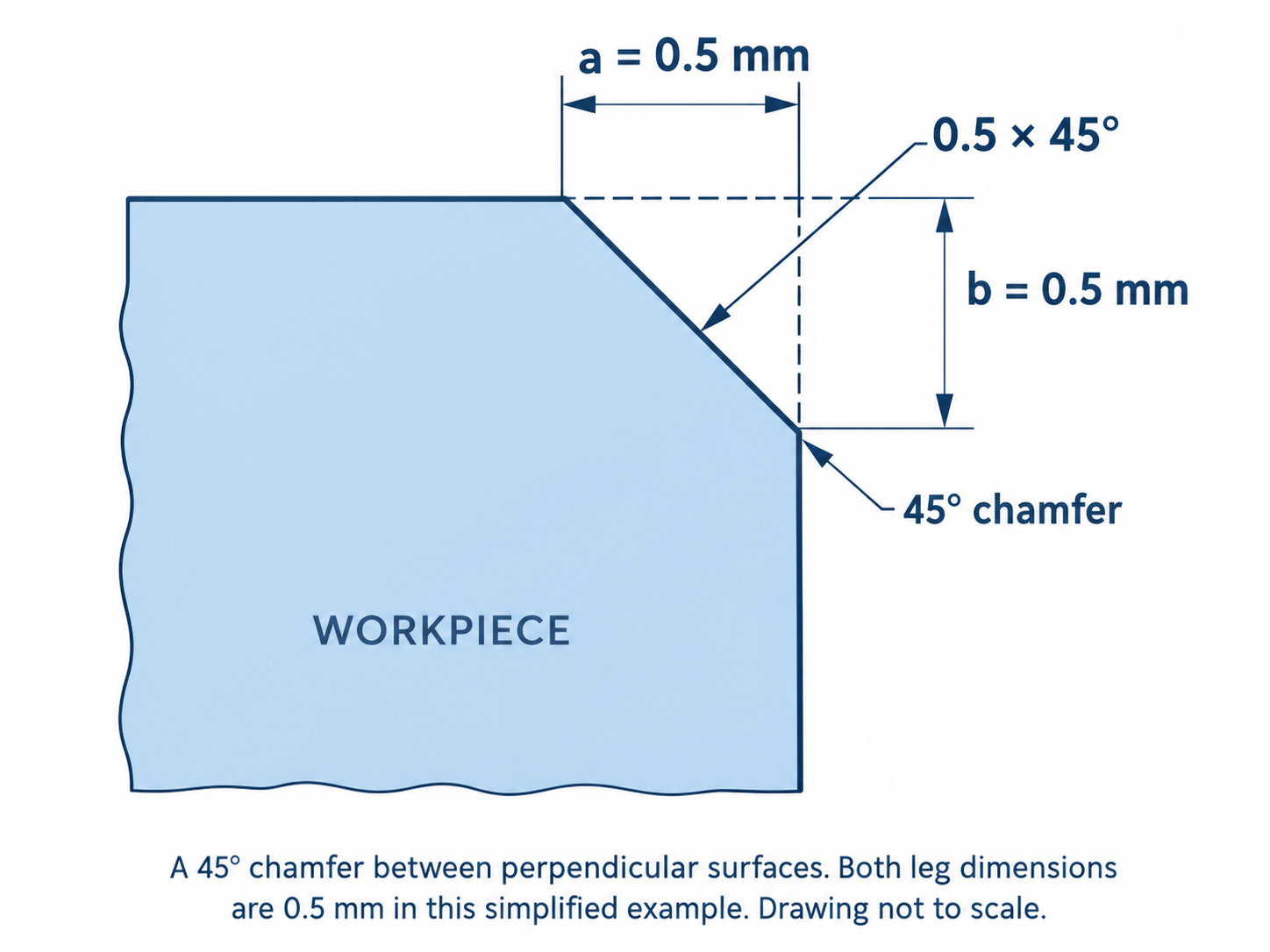
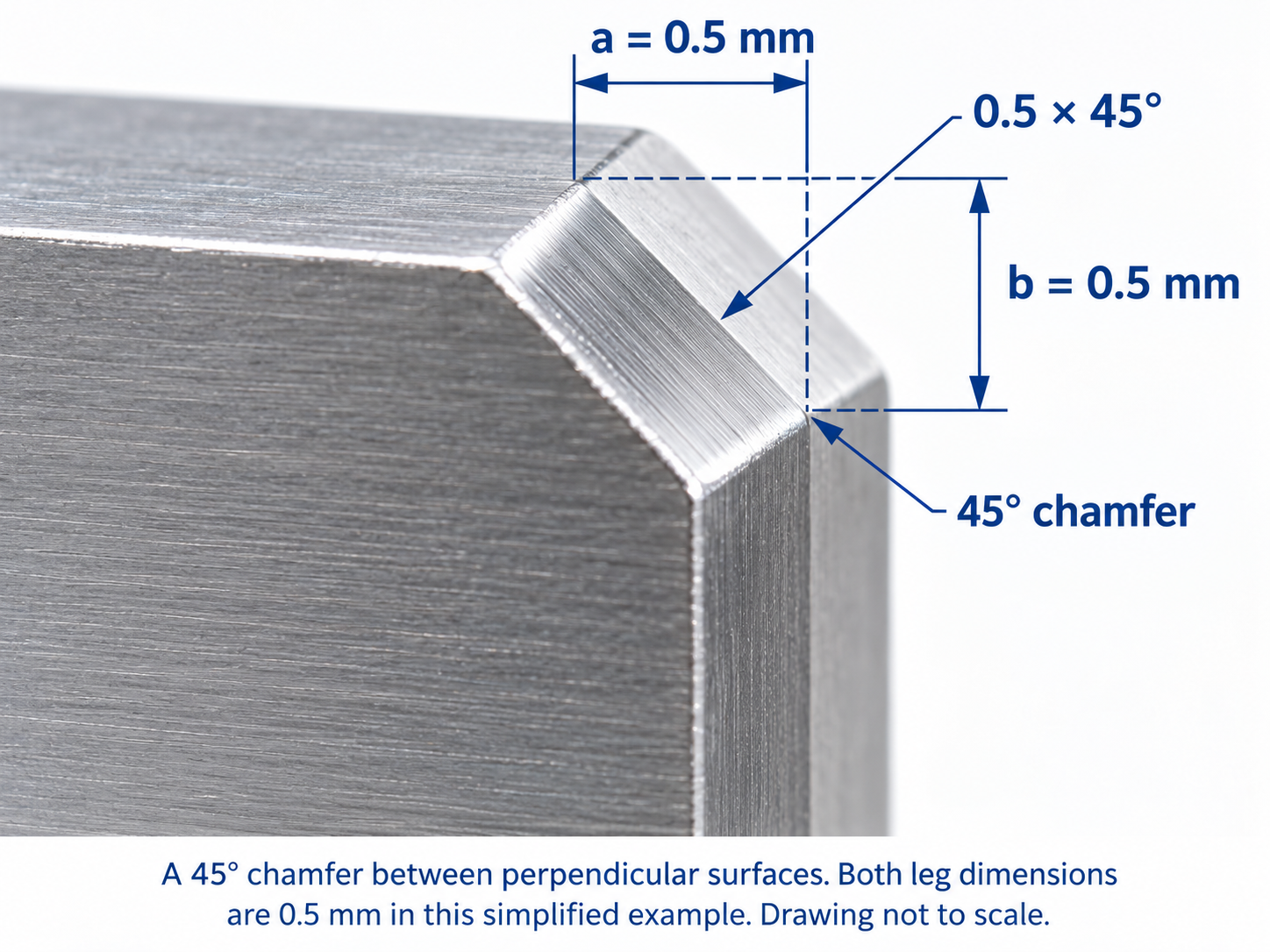
In a drawing that specifies a chamfer by leg length and angle, 0.5 × 45° specifies a nominal 0.5 mm setback at 45°. For two perpendicular original surfaces, the equal setbacks are each 0.5 mm; 0.5 mm is not the length measured along the sloping chamfer face. ISO 129-1:2018, Annex B, shows the corresponding simplified form for 45° chamfers.
Chamfer Angle, Width, and Depth
Consider a chamfer between two perpendicular surfaces. Let a be the horizontal setback and b the vertical setback. If the chamfer face forms an angle θ with the horizontal:
For a 45° chamfer, tan(45°) = 1, so a = b. If both legs are 0.5 mm, the theoretical sloped face length is:
This distinction matters because chamfer leg length, sloping face length, and CNC tool axial position are different measurements.
On a machine, the relationship between programmed depth and finished chamfer dimensions also depends on tool geometry, tool-tip condition, offsets, and the specific machining setup.
Chamfer vs Radius Callouts
A 0.5 mm chamfer and an R0.5 radius are not the same feature. A chamfer produces a planar transition; a constant-radius fillet produces a curved profile.
Replacing one with the other without design approval may affect mating clearance, appearance, contact conditions, and functional performance.
Always distinguish between a specified radius, a chamfer, and a general edge-break requirement.
5. How Is a Chamfer Cut in CNC Machining?
A chamfer cut is a machining operation that removes material along an edge to create a defined inclined surface.
In CNC milling, a chamfer mill or another suitable cutter follows the programmed edge path. The finished geometry depends on the selected tool, tool position, cutting parameters, and workpiece setup.
What Is a Chamfer Mill?
A chamfer mill is a cutting tool designed to machine angled edge features. Depending on its geometry, it may also support certain deburring, V-grooving, or related finishing operations.
Chamfer mills are available with different cutting angles, edge geometries, diameters, flute counts, substrates, and coatings. The correct choice depends on the workpiece material and the required chamfer geometry.
Tool Included Angle vs Chamfer Angle
One frequent source of confusion is the difference between a V-shaped tool's included angle and the angle made by an individual cutting flank.
For a symmetric, pointed V-tool, the included angle is twice the half-angle: for example, a 90° included angle corresponds to 45° on each side of the tool centerline. This does not mean that every manufacturer's '45°' tool designation refers to the same angle. Check the catalog diagram, tool orientation, and workpiece reference surface.
Therefore, never select a chamfering tool based only on a number such as 45° without confirming whether it represents the included angle, half-angle, or specified cutting-edge geometry.
External Edge Chamfering
External chamfering is commonly performed along the perimeter of a milled part. A suitable tool follows the selected contour at a programmed position.
Toolpath planning should consider workholding clearance, cutter diameter, entry and exit moves, corner geometry, tool deflection, and burr formation.
Hole Chamfering and Countersinking
Hole-entry chamfering creates an inclined feature around the entrance of a hole. A countersink operation generally produces a conical recess, often for a countersunk fastener.
The two operations can use related cutting geometries, but a small hole-entry chamfer should not be assumed equivalent to a specified countersink for a screw head.
How to Machine a Chamfer: Practical Workflow
- Review the drawing. Identify the required chamfer size, angle, tolerance, and location.
- Check the workpiece material. Consider hardness, machinability, burr behavior, and edge-finish requirements.
- Select the tool geometry. Confirm the cutting angle, usable diameter, edge design, and suitable tool material.
- Plan the toolpath. Account for actual tool geometry, reference surfaces, collision clearance, and tool offsets.
- Set cutting conditions. Establish suitable spindle speed, feed, engagement, and coolant or lubrication strategy where applicable.
- Perform a controlled first cut. Check the actual edge position before committing to production.
- Inspect and adjust. Measure the required chamfer characteristics, check the surface finish, and correct offsets if needed.
What Affects Chamfer Accuracy?
The finished chamfer does not depend on cutter accuracy alone. Important process factors include:
- Spindle and toolholder runout.
- Actual cutting-edge geometry and tool wear.
- Tool length and diameter offsets.
- Machine and fixture rigidity.
- Workpiece positioning and clamping.
- Cutting forces, feed rate, and vibration.
- Burr formation and inspection method.
These considerations become especially important when chamfering precision components, small features, hardened steels, or complex machined parts.
Chamfering Hardened Steel and Precision Components
When machining hardened tool steels, tool selection should account for actual hardness, material composition, edge engagement, machine stability, and surface requirements.
Cutting-tool substrate, microgeometry, coating selection, and cutting conditions can influence edge stability and tool wear. A material-specific machining assessment is preferable to using one general parameter set for every hardened steel application.
Explore the KXT cutting tool product range and machining performance case studies for further information about our precision cutting tool applications.
6. How to Choose Between a Chamfer, Bevel, and Fillet
The best edge feature depends on what the component must do, not simply which geometry is easiest to draw. Evaluate assembly, loading, safety, machining accessibility, and cost before selecting the feature.
| Design Requirement | Common Starting Choice | Reason |
|---|---|---|
| Remove a sharp machined edge | Chamfer or specified edge break | Creates a controlled edge condition |
| Guide a pin into a bore | Entry chamfer | Helps guide the mating feature |
| Prepare plate edges for welding | Specified bevel preparation | Supports the required joint geometry |
| Create a rounded transition | Fillet or radius | Provides curved geometry |
| Modify a stressed internal corner | Engineered radius where appropriate | May improve the local stress distribution |
| Meet a specific mating clearance | Drawing-defined feature | Fit determines the required geometry |
Consider Manufacturing Cost and Accessibility
A simple accessible chamfer can often be produced efficiently using a conventional CNC toolpath. Complex radii or large bevels may require additional passes, specialized tools, or different machining strategies.
However, manufacturing cost is not determined by the feature name alone. Material, tolerances, surface finish, batch size, machine capability, accessibility, and inspection requirements all affect the process.
When Is a Custom Cutting Tool Useful?
Standard cutting tools may not be appropriate for every edge profile. Restricted tool access, unusual geometries, tight tolerances, or complex workpiece materials may require a different tool design.
For non-standard cutting requirements, KXT offers OEM and ODM custom cutting tool services . Tool feasibility and suitability must be reviewed against the specific drawing and machining conditions.
7. Frequently Asked Questions
What does chamfer mean?
A chamfer is a flat angled transition that removes a sharp edge or corner between adjoining surfaces. It is often used for edge finishing, assembly, and deburring.
What is the difference between a bevel and a chamfer?
A chamfer generally describes a defined edge treatment, while bevel is a broader term for an inclined surface. Both can have flat angled geometry, and their meanings can overlap.
Are chamfered and beveled edges the same?
They can describe similar geometry. A chamfered edge is commonly a specific small beveled feature. In engineering, the actual dimensions and angle should determine manufacturing requirements.
What does bevelled vs chamfered mean?
Bevelled is a British English spelling of beveled. Both refer to an inclined edge or surface. Chamfered refers to an edge that has been given a chamfer. The technical distinction depends on context and specified geometry.
Is a chamfer always 45 degrees?
No. Although 45 degrees is common, chamfers may use other angles when required by the component design, assembly, or machining process.
What is the difference between a chamfer and a fillet?
A chamfer is a flat angled transition, while a fillet is a curved transition. A constant-radius fillet is usually specified by its radius, whereas a chamfer is commonly defined by size and angle.
What is a chamfer cut?
A chamfer cut is a manufacturing operation that removes material from an edge to create an angled flat surface. It can be produced using several machining methods, including CNC milling and turning.
What tool is used to cut a chamfer?
Common options include chamfer mills, turning tools, suitable countersinking tools, and other cutters with appropriate geometry. Selection depends on the feature, material, and manufacturing process.
Can a chamfer mill machine a bevel?
Yes, when the tool geometry, machining access, and required dimensions are compatible. Not every chamfer mill is suitable for every bevel size or configuration.
Is a chamfer better than a fillet for stress reduction?
Not necessarily. A suitably designed radius may provide a smoother stress transition in certain loaded parts. The correct choice depends on geometry, material, loading, and functional requirements.
How is a chamfer specified on an engineering drawing?
A chamfer may be specified with a size and angle, for example 0.5 × 45°. Some drawing systems use C0.5 for a 0.5 mm 45-degree chamfer. Always verify the applicable drafting convention.
Can chamfers be machined in hardened steel?
Yes, provided the tool, machine, workholding, and cutting conditions are suitable. Tool selection should consider the actual steel grade, hardness, geometry, and finish requirement.
Conclusion: Understanding Chamfer, Bevel, and Fillet
Understanding the meaning of a chamfer and the difference between a bevel and a fillet helps connect engineering design with manufacturing requirements.
Chamfers are commonly used for defined edge treatments and assembly lead-ins. Bevels describe inclined edge or surface geometry, often in a broader context. Fillets provide rounded transitions where a curved profile is needed.
The most important requirement is not the terminology alone, but the correct specification of size, angle or radius, tolerance, material, and function. These factors guide tool selection, CNC programming, and inspection.
Need Technical Support for Precision Cutting Tools?
KXT manufactures CNC cutting tools for precision machining applications, including mold manufacturing and hardened-steel machining.
If your project requires a specific cutting geometry or a customized tool, share your drawing, workpiece material, machining conditions, and required tolerances for technical review.
Contact KXT