10-32 Tap Drill Size: #21 Drill, Diameter & Tapping Guide
Need the correct drill bit for a #10-32 tap? Start with the #21 drill for conventional cut tapping, then check whether your job calls for a form tap, a clearance hole, or a different thread specification.
Quick answer: For a conventional #10-32 UNF cutting tap, the common starting drill size is #21 (0.1590 in / 4.0386 mm). A thread-forming tap (roll tap) needs a different pilot-hole diameter. Confirm the tap manufacturer's chart, the engineering drawing, and the required inspection criteria.
What Does 10-32 UNF Mean?
#10-32 UNF is a Unified National Fine inch-series screw-thread designation. It is commonly encountered on mechanical components, equipment hardware, and precision assemblies in North American manufacturing.
The #10 identifies a numbered screw size with a basic major diameter of 0.1900 in (4.826 mm). The 32 identifies 32 threads per inch, giving a pitch of 0.03125 in (0.79375 mm).
Do not confuse #10-32 UNF with #10-24 UNC. They have the same nominal major diameter but different thread pitches and different conventional cutting-tap drill sizes.
| Thread | Series | Threads per Inch | Common Cutting-Tap Drill |
|---|---|---|---|
| #10-32 | UNF (Fine) | 32 TPI | #21 (0.1590 in) |
| #10-24 | UNC (Coarse) | 24 TPI | #25 (0.1495 in) |
Source: Allied Machine & Engineering's Unified National tap drill chart. Use the drawing's full thread designation, including the required thread class where specified.
10-32 Tap Drill Size Chart
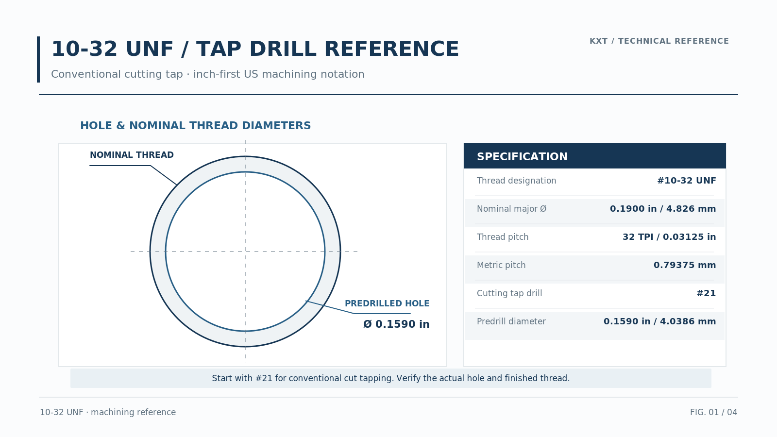
The standard starting recommendation for a conventional 10-32 UNF cutting tap is a #21 drill. Its diameter is 0.1590 in, or 4.0386 mm, using the exact inch-to-millimeter conversion.
| Specification | Value |
|---|---|
| Thread Designation | #10-32 UNF |
| Nominal Major Diameter | 0.1900 in (4.826 mm) |
| Thread Pitch | 32 TPI; 0.03125 in (0.79375 mm) |
| Recommended Conventional Cutting-Tap Drill | #21 |
| #21 Nominal Drill Diameter | 0.1590 in (4.0386 mm) |
| Final Acceptance | According to thread class, drawing and inspection requirements |
What If the Drill Is Slightly Smaller or Larger?
A smaller predrilled hole leaves more material for a cutting tap to remove and generally increases tapping load. A larger hole reduces the amount of material removed, but can also reduce thread engagement. Neither is automatically acceptable without checking the finished-thread requirements.
| Drill Size | Diameter (in) | Diameter (mm) | Relative to #21 |
|---|---|---|---|
| #22 | 0.1570 | 3.9878 | Smaller hole; generally higher cutting-tap load |
| #21 | 0.1590 | 4.0386 | Common standard cutting-tap drill |
| #20 | 0.1610 | 4.0894 | Larger hole; generally lower thread engagement |
These are nominal drill diameters, not guaranteed finished-hole sizes. Measure the actual hole when diameter control is important.
How to Calculate the 10-32 Tap Drill Size
A common shop-floor approximation for a conventional cutting tap is to subtract the thread pitch from the nominal major diameter.
Approximate Tap Drill Diameter = Major Diameter − Pitch
10-32 pitch = 1 ÷ 32 = 0.03125 in
0.1900 − 0.03125 = 0.15875 in
Nearest commonly specified numbered drill: #21 = 0.1590 in
This calculation explains the familiar #21 selection. It is an approximation for cutting taps, not a complete thread-tolerance calculation and not a method for sizing roll-tap pilot holes. The tap manufacturer's data and engineering drawing take precedence over this shortcut.
10-32 Cutting Tap vs. Form Tap: Different Pilot Holes
This is one of the most important distinctions in hole preparation. A cutting tap (cut tap) removes material to produce the internal thread. A thread-forming tap (form tap or roll tap) displaces ductile material to form the thread profile without producing thread-cutting chips.
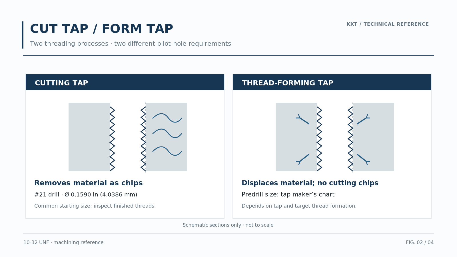
Their predrilled hole sizes are not interchangeable. In general, a form tap needs a larger and more tightly controlled pilot hole than a conventional cutting tap.
| Tapping Method | Published Reference | Important Condition |
|---|---|---|
| Conventional Cutting Tap | #21 — 0.1590 in (4.0386 mm) | Common standard starting recommendation |
| Form Tap / Roll Tap | #16 — 0.1770 in (4.4958 mm) | Haas 65%-target chart; listed approximate thread percentage is 61.2% |
| Form Tap / Roll Tap | 4.4 mm (0.1732 in approx.) | Haas roll-tap chart; listed actual thread percentage is 78.93% |
Why Do Haas Charts Show Different Form-Tap Drill Sizes?
The published examples use different thread-formation targets and reference conditions. They are not universal alternatives. Follow the specific form-tap manufacturer's recommendations, the workpiece material, and the required finished-thread limits. For tight hole requirements, drilling followed by reaming may be appropriate.
Which Type Should You Use?
Cutting taps are commonly used across a wide range of materials and applications, with geometry selected for the workpiece and hole type. Form taps can be advantageous in suitable ductile materials, but material formability, lubrication, and precise pilot-hole control are essential. Do not assume a roll tap is suitable for hardened or brittle materials.
10-32 Tapped Hole vs. #10 Screw Clearance Hole
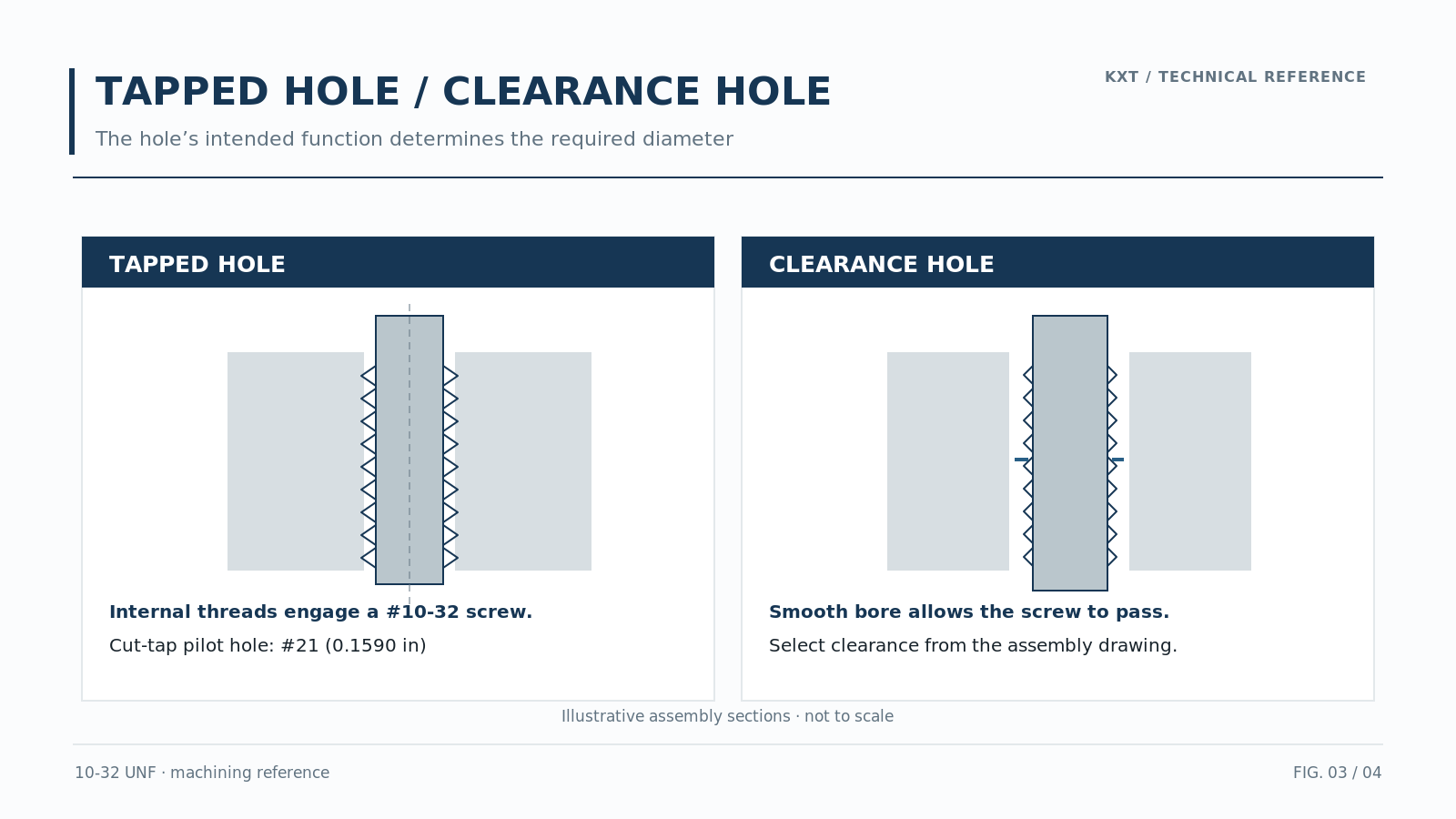
A tap drill hole is prepared for internal threads. A clearance hole is larger and allows a #10 screw to pass through without engaging the surrounding material. The clearance-hole size is chosen for the assembly fit, not from the tapping chart.
| Fit | Drill Size | Nominal Diameter (in) | Nominal Diameter (mm) |
|---|---|---|---|
| Close Clearance | #5 | 0.2055 | 5.22 |
| Normal Clearance | #2 | 0.2210 | 5.61 |
| Loose Clearance | B | 0.2380 | 6.05 |
These are commonly published nominal drill references for #10 screw clearance holes, not cutting-tap pilot holes. Clearance-hole tolerances and fit must follow the engineering drawing and applicable standard. For a conventional 10-32 cutting-tap pilot hole, use the separate #21 reference above.
How Material and Hole Type Affect 10-32 Tapping
Material affects cutting forces, chip behavior, friction, and tool selection. However, the material name alone does not justify an arbitrary change to the required thread dimensions. Start with the correct tap type and thread specification, then refine the machining process.
Aluminum and Other Ductile Alloys
Pay attention to chip adhesion, burrs, and lubricant choice. Both cutting taps and form taps may be options in suitable alloys; each requires its own pilot-hole recommendation. Verify finished-thread quality rather than assuming the nominal drill guarantees the result.
Carbon and Alloy Steels
Select drilling and tapping tools for the material condition, machine rigidity, hole depth, and production requirements. Check the actual drilled diameter, cutting fluid strategy, and tap wear. Do not substitute an unverified drill size just to reduce cycle time.
Stainless Steel
Austenitic grades such as 304 and 316 can work-harden during machining. Sharp tools, suitable feeds, lubrication, and chip control are important. Using a smaller cutting-tap pilot hole generally increases rather than decreases the material-removal load. Any change to hole size must preserve the specified thread requirements.
Blind Holes and Through Holes
A through hole permits chips to leave the far side when the chosen tapping method and geometry allow it. A blind hole needs extra attention to chip evacuation, tap chamfer length, usable thread depth, and bottom clearance. Match the tap geometry and programmed depth to the hole design.
Hole Accuracy and Inspection
Drill diameter is not the same as finished-hole diameter. Runout, toolholder condition, deflection, material response, and wear can all affect the hole. Inspect the predrilled hole when necessary. Verify the finished internal thread using the specified thread gage and acceptance criteria, such as an appropriate GO/NO-GO thread plug gage for the required thread class.
CNC Hole-Preparation Checklist Before Tapping
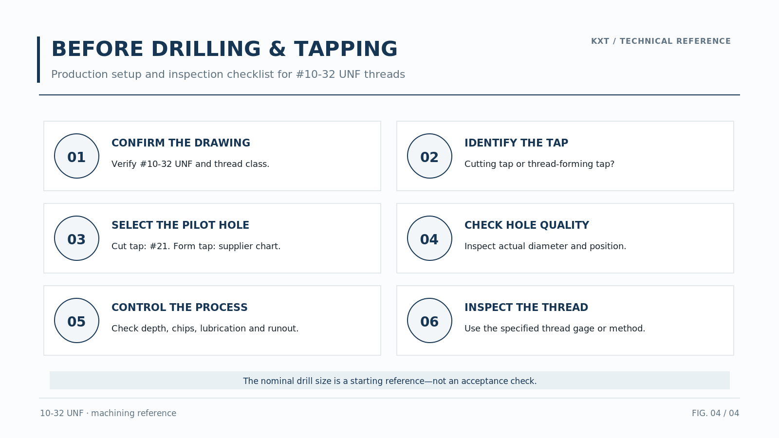
- Read the callout: Confirm #10-32 UNF rather than #10-24 UNC, and identify the required thread class if specified.
- Identify the process: Cutting tap or thread-forming tap? Do not share the same default pilot-hole diameter.
- Check the drawing: Confirm thread depth, blind-hole or through-hole condition, and any hole-size or positional requirements.
- Select the drill: Start with the tool manufacturer's recommendation for the actual workpiece material and tapping process.
- Control the setup: Review toolholder runout, tool condition, feeds, lubrication, and chip evacuation.
- Measure and verify: Check representative predrilled holes and inspect finished threads using the specified method.
For higher-risk parts, validate the process on a sample before releasing a production batch. A nominal drill-size chart is a starting reference, not a substitute for process qualification.
Frequently Asked Questions About 10-32 Tap Drill Size
What Size Drill Bit Do I Need for a 10-32 Tap?
For a conventional #10-32 UNF cutting tap, use a #21 drill (0.1590 in / 4.0386 mm) as the common starting recommendation. Confirm the tap manufacturer's chart and drawing requirements.
Is 10-32 UNC or UNF?
#10-32 is UNF (fine thread). The common #10 coarse-thread designation is #10-24 UNC.
Can I Use a 4 mm Drill for a 10-32 Cutting Tap?
A 4.00 mm drill is slightly smaller than the #21 nominal diameter of 4.0386 mm. That difference can increase cutting-tap load. Use it only when the tap manufacturer's guidance and finished-thread inspection support the substitution.
Can I Use a 4.1 mm Drill for a 10-32 Cutting Tap?
A 4.10 mm hole is slightly larger than the #21 nominal diameter and generally produces less thread engagement. It is not an automatic substitute. The specified internal thread must still pass the applicable inspection criteria.
What Size Drill Do I Use for a 10-32 Form Tap?
There is no universal answer independent of the tap and target thread formation. Haas publishes a #16 drill (0.1770 in) in its 65%-target form-tap chart, as well as a 4.4 mm reference in a separate roll-tap chart. Follow the chart for the specific forming tap and application.
Is the Drill Size for 8-32 the Same as 10-32?
No. A conventional #8-32 UNC cutting tap commonly uses a #29 drill (0.1360 in). A #10-32 UNF cutting tap commonly uses a #21 drill (0.1590 in).
Why Does a 10-32 Tap Break Even With a #21 Drill?
The nominal drill size is only one variable. Possible causes include an undersized actual hole, misalignment, unsuitable tap geometry, chip packing, insufficient blind-hole clearance, lubrication problems, or excessive tapping load. Inspect the hole and setup before changing drill size.
How Do I Check the Finished 10-32 Internal Thread?
Follow the drawing's thread class and inspection plan. A suitable GO/NO-GO thread plug gage is a common acceptance method for internal threads. Critical components may require additional dimensional or functional verification.
Technical References and Source Notes
The dimensional references above are drawn from published manufacturer charts and hole-size references. Different tapping methods and thread-formation targets have intentionally been kept separate.
- Allied Machine & Engineering — Unified National Tap Drill Charts (PDF) . Confirms #10-32 UNF / #21 and #10-24 UNC / #25.
- Haas Automation — Inch Form Tap Drill Size Chart (PDF) . Includes the #10-32 / #16 / 0.1770 in form-tapping reference.
- Haas Tooling — Roll Tap Drill Size Chart (PDF) . Lists #10-32 / 4.4 mm / 78.93% actual thread. The chart is a starting reference.
- ASME B18.2.8 — Clearance Holes for Bolts, Screws, and Studs . Defines close, normal, and loose clearance-hole categories.
- True Precision Machining — Clearance-Hole Reference Chart . Provides the #10 clearance drill numbers #5, #2, and B shown in the table.
Reference values are educational starting points. The applicable engineering drawing, thread specification, tool manufacturer's recommendations, and verified process capability govern production decisions.
Cutting Tool Selection and Technical Support
KXT manufactures solid carbide cutting tools and provides application-based tooling support. For tooling requirements involving special hole preparation or related cutting operations, provide the workpiece material, dimensions, tolerances, machine details, and expected production conditions for review.
Explore KXT cutting tools , learn about custom cutting-tool services , or contact KXT to discuss your application.