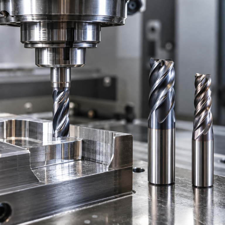
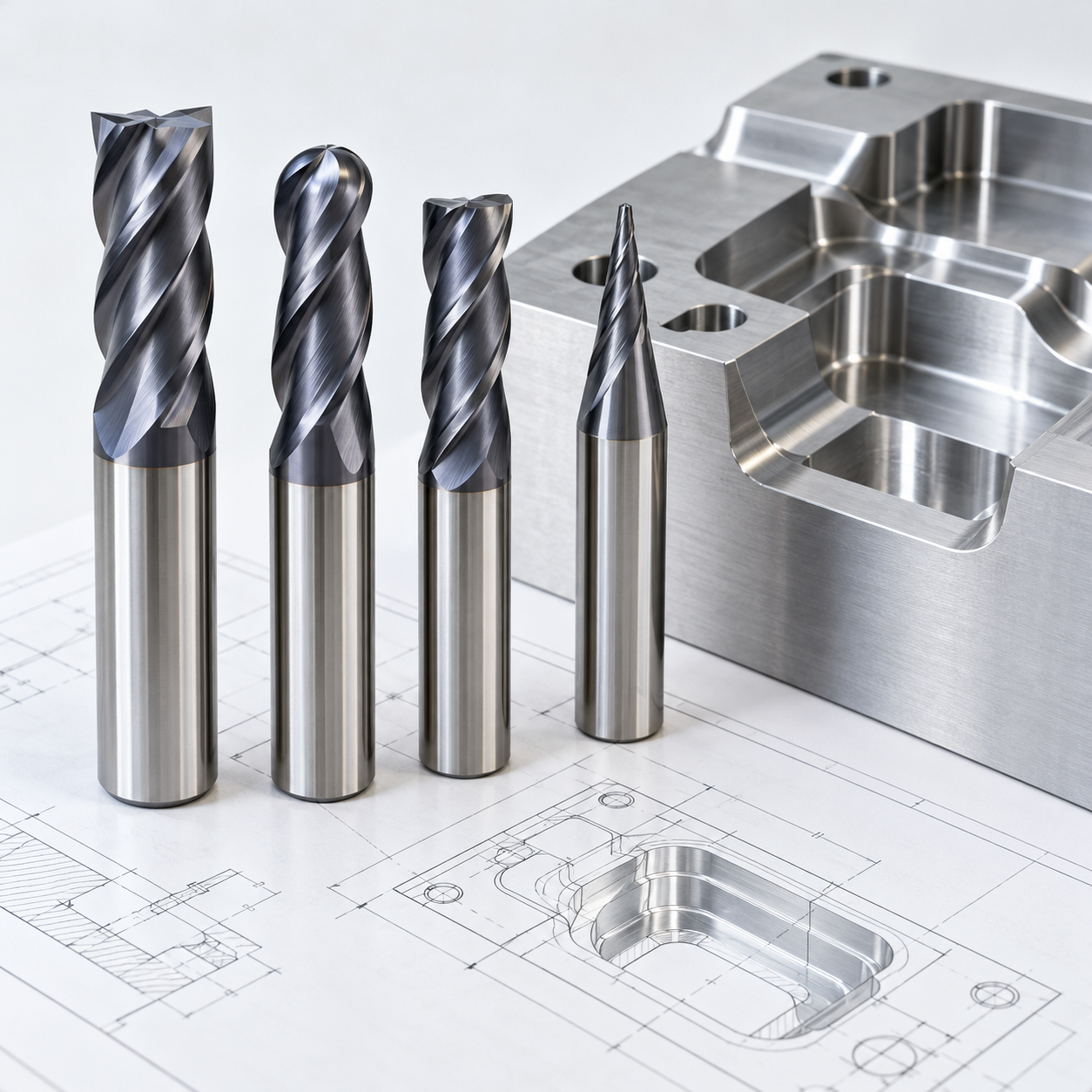
Complete Guide to Carbide End Mill Selection
Complete Guide to Carbide End Mill Selection explains how to choose a solid carbide end mill based on material, hardness, operation, cutter dimensions, geometry, coating and cutting conditions.
This is the main selection guide in the KXT technical resource collection. Use it to follow a complete decision process, then open the linked specialist articles for more detailed technical information.
KXT / Taizhou Tengli Tools — CNC cutting tools for precision milling and mold machining.
Quick Answer: How Do You Select a Carbide End Mill?
Selecting a carbide end mill is not about picking the most expensive cutter or matching one coating to one material. It is a practical selection process that starts with the workpiece and ends with a measured, repeatable process:
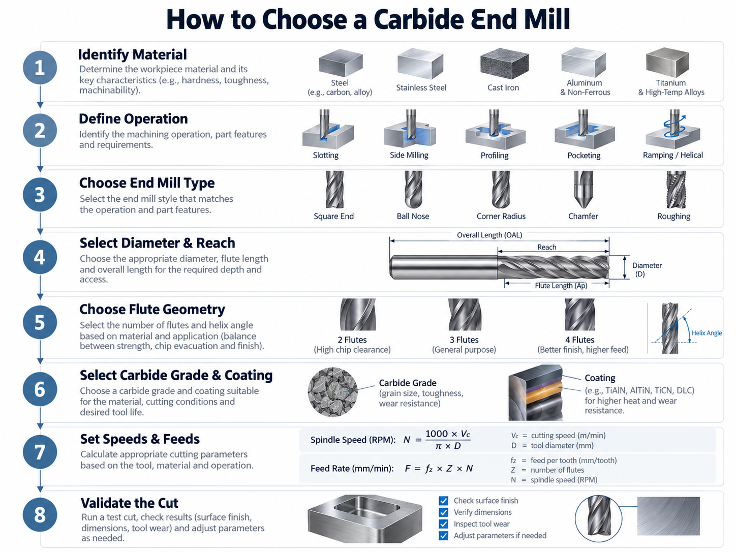
- Identify the workpiece — exact grade, condition and hardness.
- Define the operation and feature — slot, pocket, shoulder, contour or 3D surface, plus finish and tolerance targets.
- Determine cutter dimensions — diameter, flute length, reach and minimum overhang.
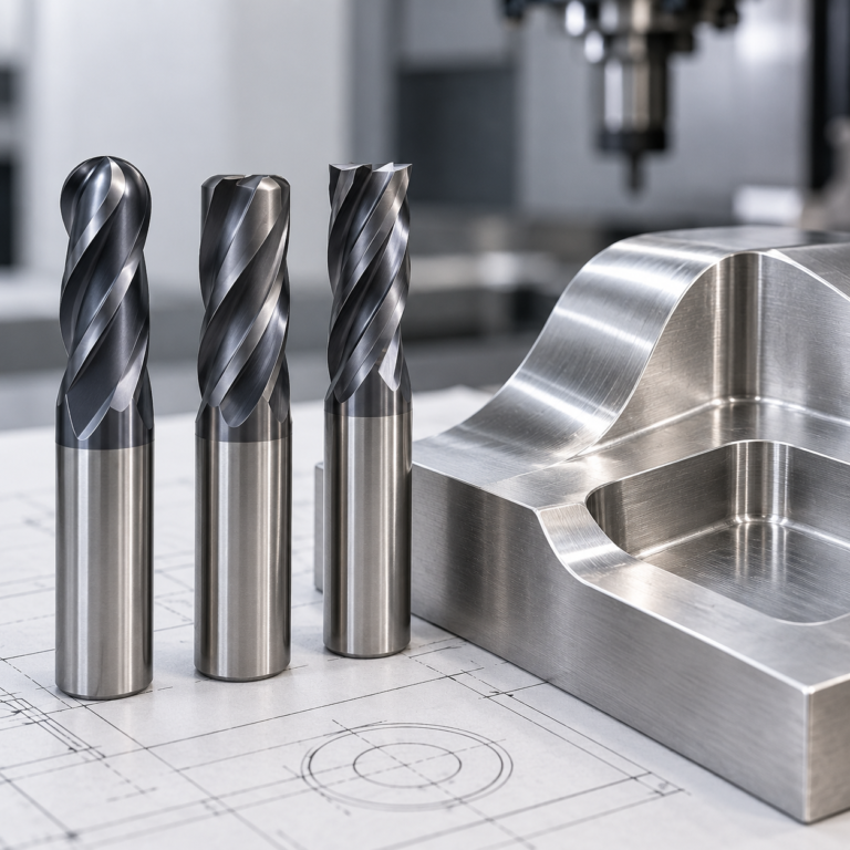
- Choose the end mill type — square, corner-radius, ball-nose, roughing, tapered or chamfer.
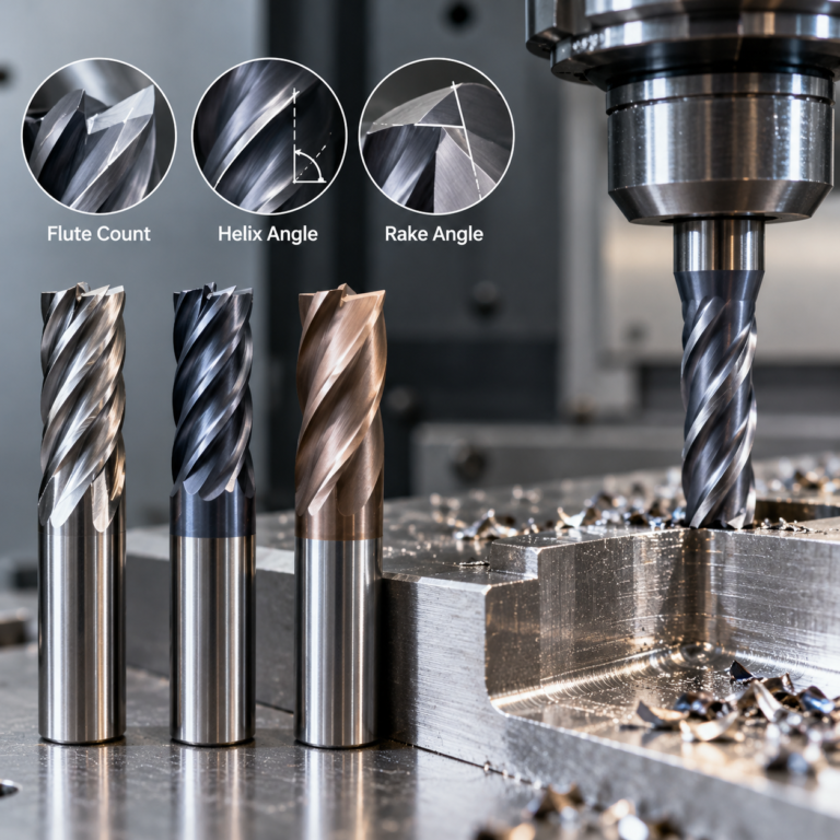
- Choose flute count and cutting geometry — chip space, helix, pitch, rake, edge preparation and core strength.
- Choose the coating — matched to the dominant failure mode.
- Calculate speeds and feeds and build a rigid setup — toolholder, runout, overhang, coolant and toolpath.
- Validate the cut and troubleshoot from evidence — inspect the edge and the surface before changing parameters.
This guide owns the complete decision flow. Each deep technical topic links to a dedicated KXT article where the full detail lives, so you can go as deep as the job requires without losing the overall sequence.
Carbide End Mill Selection Chart by Material
This table is a screening aid, not a universal set of machining parameters. Verify the actual tool series and cutting conditions before production.
| Workpiece | Typical flute direction | Geometry priority | Coating direction |
|---|---|---|---|
| Aluminum / non-ferrous | 2–3 for many slotting applications | Open polished flutes; efficient evacuation | Uncoated, qualified TiB2 or ZrN |
| Carbon / alloy steel | Often 4–5, depending on engagement | Balanced core, supported edge | Qualified TiAlN, AlTiN or AlCrN |
| Stainless steel | Often 3–5, depending on operation | Controlled edge preparation; reliable chip flow | Application-qualified PVD system |
| Cast iron | Often 4–6 | Abrasion resistance and stable edge support | Wear-resistant coating matched to cast-iron grade |
| Titanium alloys | Tool-series and operation dependent | Heat and adhesion control; suitable coolant | Qualified coating for titanium |
| Hardened tool steel, approx. 45–65 HRC | Often 4–7 for suitable finishing / low radial engagement | Short rigid tool, reinforced edge and steady engagement | Hard-milling-grade PVD system |
The appropriate flute count changes with slotting, finishing and high-efficiency milling even for the same workpiece.
Step 1 — Identify the Workpiece Exactly
The workpiece is the single biggest driver of end mill selection. A label such as "steel" or "stainless" is not enough: two alloys in the same family can demand opposite geometry. Before opening a tool catalog, record four facts:
- Exact grade — for example 6061-T6 aluminum, 304 austenitic stainless, 4140 alloy steel, Ti-6Al-4V or Inconel 718.
- Condition — hot rolled, cold drawn, annealed, normalized, quenched and tempered, aged or hardened.
- Hardness — measured in HRC, HB or HV. A 4140 at 22 HRC and the same grade at 45 HRC are different applications.
- Material behavior — gummy and long-chipping, abrasive, work-hardening, heat-resistant or already hardened.
| Material group | Typical behavior | Dominant machining risk |
|---|---|---|
| Aluminum and non-ferrous alloys | Soft, long chips, high achievable speed | Chip packing, built-up edge, recutting |
| Low-carbon and mild steels | Free-machining, continuous chips | Built-up edge, flank wear |
| Alloy steels | Higher strength, heat-treated conditions | Heat, corner chipping, deflection |
| Stainless steels (304, 316, 17-4 PH) | Ductile, work-hardening, sticky | Work hardening, notching, heat, built-up edge |
| Cast irons | Short chips, abrasive graphite | Abrasive flank wear, edge chipping |
| Titanium alloys | Low thermal conductivity, adhesion | Concentrated heat, notch wear |
| Nickel-based superalloys | High strength at temperature, hardening | Notch wear, thermal cracking, sudden failure |
| Hardened tool and mold steels | 45–65 HRC, high cutting pressure | Micro-chipping, deflection, rapid wear |
Why this matters: hardness and strength set the cutting speed, the required edge strength and the coating. Get the grade wrong and every later step is built on the wrong foundation.
Step 2 — Define the Operation, Feature and Production Target
The same workpiece can require different cutters depending on what is being made. Document the operation and the geometry of the feature before comparing tools.
2.1 Define the operation and machining stage
- Roughing prioritizes metal removal rate (MRR); chip load and chip volume are the main constraints.
- Semi-finishing leaves a uniform stock allowance for the finish pass, typically a few tenths of a millimeter.
- Finishing prioritizes surface finish, dimensional accuracy and edge stability at controlled engagement.
- Slotting approaches 100% radial engagement and is the most demanding operation for chip evacuation.
- Shoulder and side milling use partial radial engagement, which allows more flutes and higher table feeds.
- Pocketing, ramping and helical entry require a center-cutting end mill and an approved entry strategy.
- 3D contouring uses ball-nose tools where the effective cutting diameter changes along the profile.
2.2 Record the feature geometry
- Minimum internal corner radius — this sets the maximum cutter diameter.
- Slot or pocket width, depth and any draft angle.
- Wall and floor thickness, including thin walls that can flex.
- Required reach and any nearby clamps or fixtures that could interfere.
- Surface finish target (Ra or Rz) and tolerance band.
2.3 Set one primary production target
Maximum removal rate, longest tool life, best finish, unattended reliability and lowest cost per part do not always point to the same tool. Choose the primary target before comparing series; the remaining targets become constraints rather than competing goals.
Step 3 — Choose the End Mill Type
With the workpiece and feature defined, select the end profile that produces the required geometry. The end profile decides the shape left on the part; diameter, flutes and coating are decided afterward.
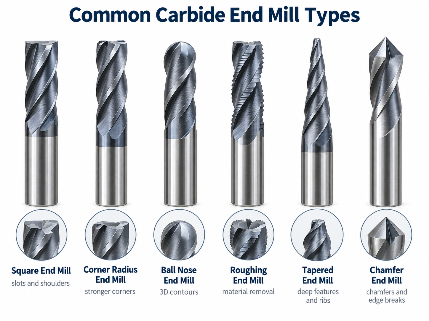
| End mill type | Primary role | Selection risk to check |
|---|---|---|
| Square end mill | Slots, shoulders, profiles and flat-bottomed pockets | Concentrated stress at the sharp 90° corner |
| Corner-radius (bull-nose) end mill | Roughing and profiling where a fillet is allowed | Programmed radius must match the actual radius |
| Ball-nose end mill | Molds, dies and 3D freeform contours | Effective diameter and local speed vary across the ball |
| Roughing end mill | High-volume stock removal with serrated edges | Leaves a serrated surface that needs finishing |
| Tapered end mill | Drafted walls, mold ribs and deep tapered features | Taper, tip diameter and CAM reference point |
| Chamfer end mill | Bevels, edge breaks and countersinks | Included angle and tip form must match the print |
| Center-cutting end mill | Ramping, helical interpolation and approved plunge | Straight plunging still confines chips at the center |
If you are choosing between a hemispherical cutter for 3D contours and a flat-ended cutter with radiused corners for pockets or floor-to-wall fillets, see our Ball Nose vs Bull Nose (Corner Radius) End Mill comparison. It explains the cutting profiles, fillet selection, surface finish and CAM tool definitions.
Carbide versus HSS
Solid carbide end mills are stiffer, harder and retain hardness at elevated cutting temperature, which makes them widely used in modern CNC, small-diameter machining, hardened materials and precision finishing. Carbide is less forgiving of shock, runout and weak workholding. High-speed steel (HSS) is tougher and remains useful for repair work, interrupted cuts with impact and machines that cannot run carbide speeds. Compare the two on total cost per part — tool life, change time, scrap and machine utilization — not purchase price alone.
For the full breakdown of every cutter profile, center-cutting geometry and the carbide-versus-HSS decision, read Types of End Mills: Geometry, Uses and CNC Selection.
Step 4 — Select Tool Diameter, Flute Length and Reach
Tool dimensions affect feature access, rigidity, toolholder compatibility and machining accuracy. Cutting diameter, flute length, reach and overall length should not be treated as interchangeable specifications.
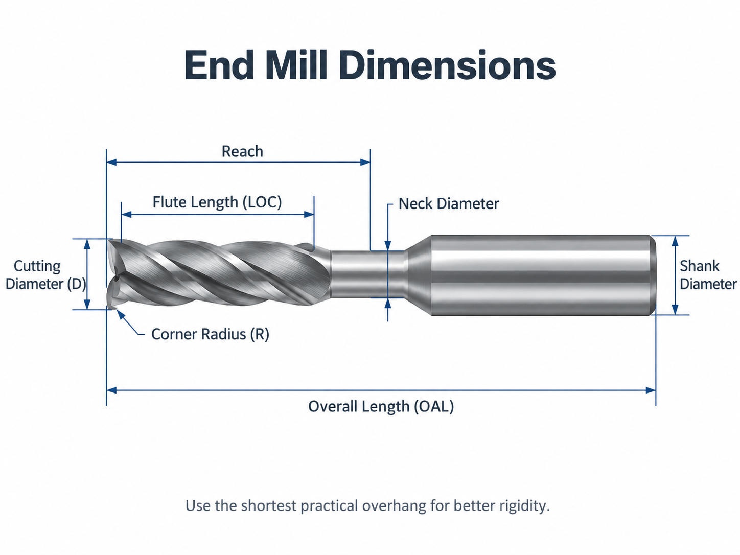
| Dimension | Meaning | Selection consideration |
|---|---|---|
| Cutting diameter (D) | Nominal diameter of the cutting portion | Feature access, tool stiffness, cutting-speed calculation |
| Flute length / LOC | Axial length of peripheral cutting edges | Available axial cutting engagement |
| Reach | Clearance distance before the neck or shank interferes | Access to deep cavities and obstructed features |
| Neck diameter | Reduced diameter behind the cutting portion, if present | Clearance versus tool deflection |
| Shank diameter | Clamping-section diameter | Toolholder fit and clamping arrangement |
| Overall length (OAL) | Length from cutting tip to shank end | Reach, projection and machine clearance |
Choose the largest practical diameter that fits the feature
The tool must fit slots, pockets and internal corners while leaving an appropriate machining allowance. A larger diameter can increase stiffness, but the part geometry, cutter path and machine limits still determine the final choice.
Use only the flute length and reach required
Longer flutes and greater unsupported projection can increase tool flexibility. A reduced-neck or tapered-reach tool may provide clearance for deep mold features without unnecessary cutting-edge length.
In an idealized cantilever model, tool deflection increases approximately with the cube of unsupported length for the same load and cross-section. Actual cutter stiffness also depends on flute, core, neck and holder geometry.
Practical selection: choose the shortest usable projection while maintaining collision clearance. Confirm the effective reach and neck clearance in CAM before cutting a deep feature.
Step 5 — Choose Flute Count and Cutting Geometry
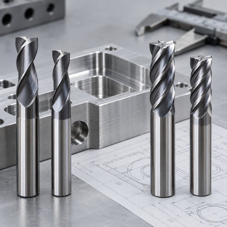
Flute count changes three things at once: the volume available for chips, the number of edge engagements per revolution and the size of the supporting core. The traditional rule of thumb — two flutes for aluminum and non-ferrous, four flutes for steel — is a useful starting point, not a universal law.
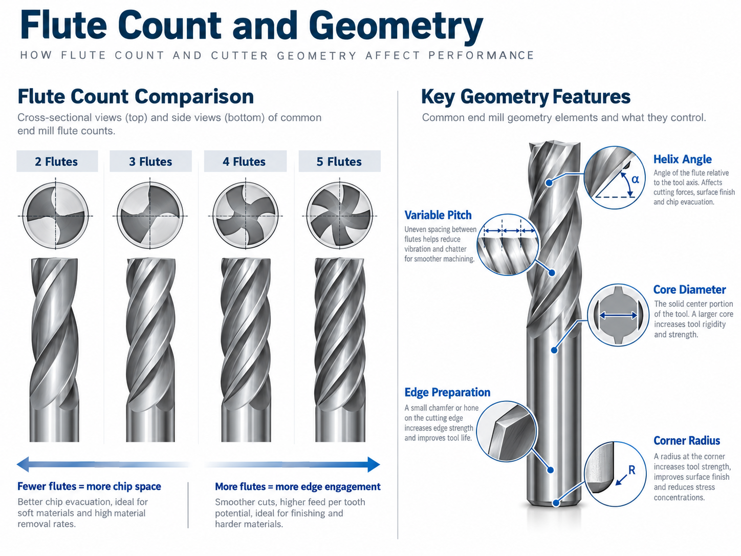
| Flute count | Strengths | Conditions to monitor |
|---|---|---|
| 1–2 flutes | Large open valleys for bulky chips; full-width slotting; O-flute designs for plastics | Fewer edges and a smaller core; lower feed at the same chip load |
| 3 flutes | Balanced chip space and edge count; common choice for aluminum and general non-ferrous work | Still needs controlled feed in deep slots |
| 4 flutes | General-purpose balance for steel, stainless and most side milling | Chip packing in deep or full-width cuts |
| 5 flutes | High-feed finishing and stainless/high-temp alloys at controlled engagement | Reduced valley volume; feed demand rises |
| 6–7+ flutes | High-efficiency milling, light-radial finishing and hard-milling toolpaths | Only suitable at low radial engagement with reliable evacuation |
At a fixed spindle speed and feed per tooth, adding flutes increases the required table feed:
Feed rate = feed per tooth (fz) × number of flutes (z) × spindle speed (RPM)
If the machine cannot maintain the calculated feed, actual chip thickness falls and the edge can rub instead of cutting. Conversely, a four-flute tool can run well in aluminum in a light radial finishing pass, while two or three flutes remain the safer choice for deep, full-width slots. Choose flute count from the engagement pattern and the chip, not from the material name alone.
For application-specific guidance on chip evacuation, core stiffness, aluminum and steel milling, and feed-rate calculations, read our 2 Flute vs 4 Flute End Mill comparison.
Once the type and flute count are set, the geometry defines how the cutter enters the work, forms the chip and responds to vibration. Every geometry choice is a trade-off.
- Helix angle: a standard helix is around 30°. A high helix (roughly 35–45° and above) engages gradually, improves chip lifting and wall finish, and suits gummy materials such as aluminum and stainless, but it increases axial force and pull-out risk. Lower-helix designs provide a different balance of edge support and axial cutting force and may be selected for some hard or brittle materials.
- Variable helix and variable pitch: changing the helix or the angular spacing between teeth breaks the regular pattern of tooth impacts and can widen the stable, chatter-free speed range. Neither compensates for poor clamping, runout or excessive overhang.
- Rake angle: a more-positive rake shears the material with lower cutting force but leaves less support behind the edge; a less-positive or negative rake strengthens the edge for hard steel and interrupted cuts.
- Edge preparation: a sharp edge cuts freely in soft materials; a hone or T-land chamfer strengthens the edge against micro-chipping in hard or abrasive work.
- Core diameter: a larger core increases bending and torsional stiffness but reduces chip volume; a smaller core opens the valleys for heavy chips.
- Corner radius: a radius replaces the fragile sharp corner with supported carbide. Choose the radius from the component drawing, cutting load and tool specification; verify that the CAM radius matches the actual ground radius.
- Reach and neck: flute length is the cutting portion; reach is how far the tool can enter before the neck or shank contacts the part. Use a reduced-neck tool only when the feature requires it.
For the complete mechanics of each feature — including tooth-passing frequency, radial and axial rake, progressive cores and application starting points — read End Mill Geometry Explained: Flutes, Helix, Pitch, Rake Angle and Core Diameter.
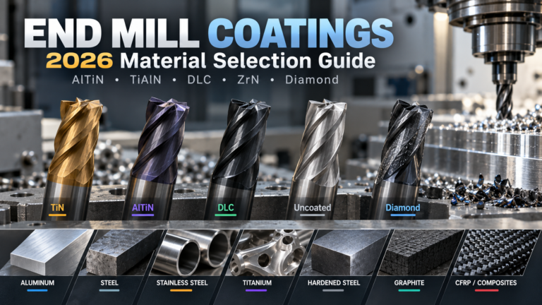
Step 6 — Select the Carbide Substrate and Coating
A coating reduces friction, slows abrasive wear, resists oxidation and changes how heat moves through the cutting zone. It cannot correct the wrong geometry, missing chip space, excessive runout or a weak setup. Coating follows geometry, never the reverse.
| Coating | Typical characteristics | Starting applications |
|---|---|---|
| Polished uncoated | Keenest edge, low aluminum affinity, smooth chip flow | Aluminum slots, copper, unfilled plastics |
| TiN | General wear-resistance baseline; gold in color | Moderate-speed general ferrous work |
| TiCN | Higher hardness and abrasive-wear resistance than TiN | Steels and abrasive work at controlled temperature |
| TiAlN | Balanced hot hardness and thermal stability | Steels, stainless, cast iron, difficult alloys |
| AlTiN | Aluminum-rich; high oxidation resistance and hot hardness | Alloy and tool steels, titanium, nickel alloys, hard milling |
| AlCrN | Thermal stability in demanding wet or dry cycles | Steel, stainless, cast iron, hardened materials |
| TiB2 / ZrN | Low chemical affinity to aluminum; anti-adhesion | Aluminum, magnesium, brass and bronze |
| DLC | Low friction, strong anti-adhesion in qualified formulations | Non-ferrous metals and selected polymers |
| CVD diamond | Extreme abrasion resistance | Graphite, CFRP, green ceramics, abrasive composites |
TiAlN versus AlTiN — the key distinction
Both are aluminum-titanium nitride PVD coatings. In general usage, AlTiN and TiAlN are names used for titanium-aluminum nitride coating families. Some naming systems distinguish them by composition, but exact chemistry and layer structure depend on the supplier. Suppliers use different ratios, layer structures and brand names, so compare full specifications rather than the labels. For aluminum, low-adhesion coating systems or polished uncoated geometries are often more appropriate. Diamond-coated tools are typically selected for suitable abrasive non-ferrous and non-metallic work, not conventional ferrous milling.
For the full coating matrix by material, PVD versus CVD detail and the cautions on same-name coatings, read End Mill Coatings: CNC Milling Material Selection Guide.
Step 7 — Calculate Speeds and Feeds, Then Build the Setup
A correctly selected cutter will still fail if it is run at the wrong parameters or held in a weak assembly. This step converts the selection into machine values and verifies the physical system around the tool.
7.1 Start from tool-specific cutting speed data
Use the cutting-speed range specified for the actual cutter series, workpiece grade, hardness and milling operation. A universal SFM table cannot account for differences in substrate, geometry, coating, chip load, engagement and machine setup.
7.2 Calculate RPM and feed rate
Imperial (inch) programming:
RPM = (SFM × 3.82) ÷ cutter diameter
Metric programming, where Vc is in m/min and diameter D in mm:
RPM = (Vc × 1,000) ÷ (π × D)
Then calculate the table feed:
Feed rate = RPM × z × fz
Worked example: a 1/4 in, three-flute end mill at 800 SFM with 0.002 in per tooth gives RPM = (800 × 3.82) ÷ 0.25 ≈ 12,224 and a feed of 12,224 × 3 × 0.002 ≈ 73 IPM.
7.3 Compensate for radial chip thinning
When radial engagement (ae) is less than half the cutter diameter, the actual maximum chip thickness is lower than the programmed feed per tooth — this is radial chip thinning. Increase the programmed feed to restore the intended chip thickness. High-efficiency milling (HEM), also called dynamic or adaptive milling, deliberately runs this way: low radial engagement (often 5–15% of diameter), deep axial cuts (up to roughly 1–2× diameter) and high feed, which keeps the cutting zone cooler and uses more of the flute length.
7.4 Choose the milling direction and toolpath
Climb milling — the cutter rotates with the feed direction — is the default on CNC machines with backlash control: it gives a better finish, lower edge load and generally longer tool life. Conventional (up) milling still has a place on machines with backlash, against heavy scale or hard skin, and in selected hard or chatter-prone materials. Use ramping or helical interpolation rather than straight plunging for entry, and consider constant-engagement or trochoidal toolpaths to smooth load spikes in corners.
7.5 Control holder, runout, overhang and coolant
- Toolholder: use clean, precision collets, shrink-fit or high-quality hydraulic holders; a Weldon flat with a side-lock holder gives security against pull-out on heavy cuts. Insert the shank to roughly 2–3 times its diameter where possible.
- Runout: measure it near the cutting end. Runout overloads one flute, which then chips first; it is especially damaging on micro end mills.
- Overhang: use the shortest functional stickout. Bending deflection scales with the cube of overhang and inversely with the fourth power of diameter, so small changes in length and diameter have large effects.
- Workholding: secure the part against climb-milling forces and support thin walls and floors before cutting.
- Coolant: use flood, through-tool coolant, air blast or MQL according to the material. Titanium and nickel alloys depend on reliable coolant delivery; if milling wet, keep the flow consistent to avoid thermal cracking from intermittent cooling.
Step 8 — Validate the Cut and Troubleshoot from Evidence
Never accept a setup based on the first good-looking chip. Run a controlled first-article check, inspect the edge under magnification and measure the result. Change one variable at a time — changing feed, speed, coolant and geometry together makes the true cause impossible to identify.
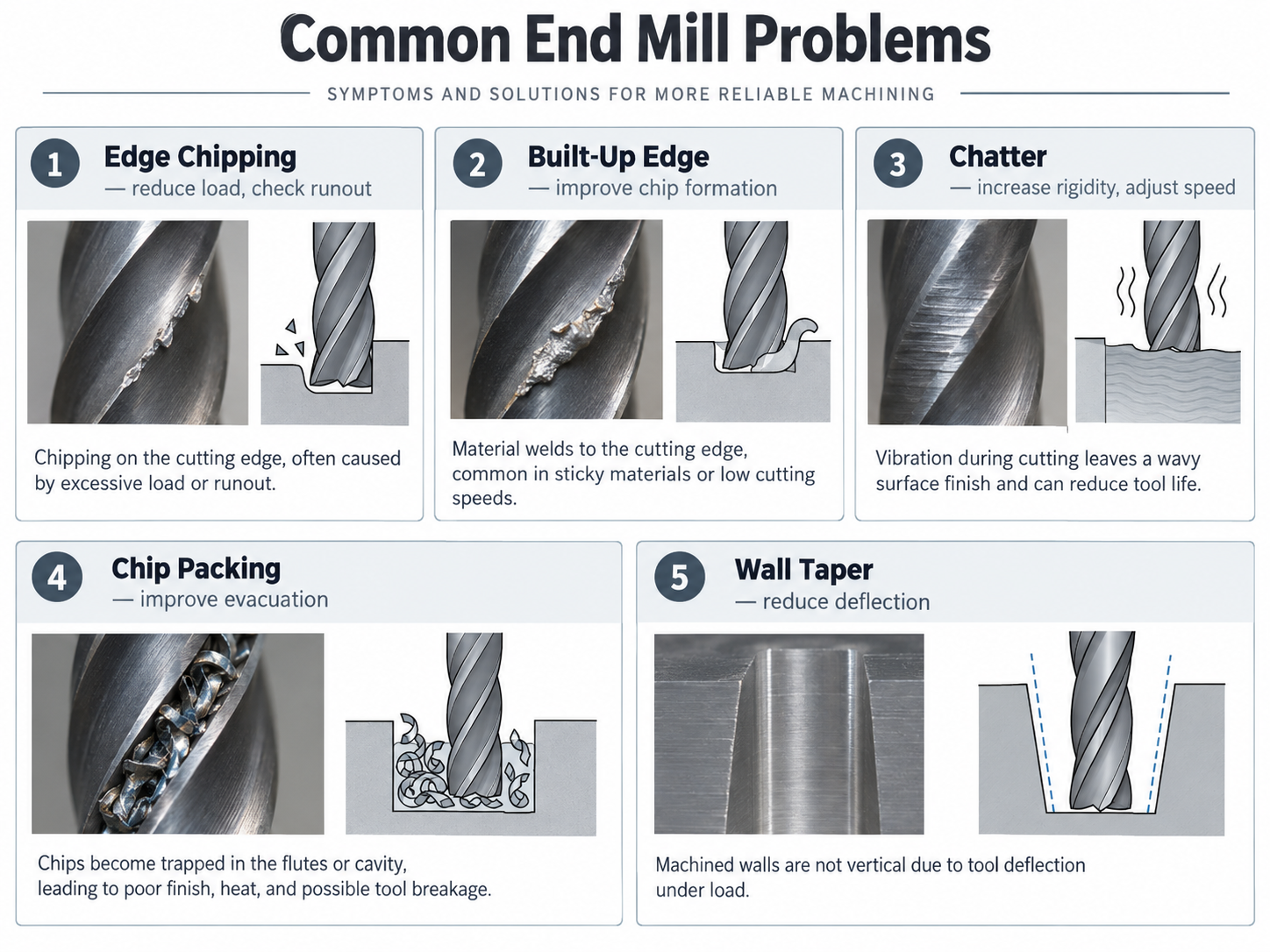
| Symptom | Most likely causes | First controlled action |
|---|---|---|
| Edge micro-chips or snaps immediately | Chip load too high, aggressive entry, runout, unsupported sharp edge | Verify chip load and runout; reduce engagement or use a honed edge / corner radius |
| Material welds to the edge (built-up edge) | Speed or feed too low, rubbing, wrong coating | Increase speed or feed; use polished flutes or TiB2/ZrN; improve coolant |
| Chips packed in the flutes | Too many flutes, deep slot, weak evacuation | Use fewer flutes, air blast or coolant; reduce axial depth |
| Regular chatter marks or sound | Speed near a stability limit, engagement spike, low rigidity | Test spindle speed while holding chip load; shorten overhang; use variable helix/pitch |
| Wall taper or dimensional drift | Deflection from overhang or load, core too small | Shorten stickout, reduce radial engagement, use a larger diameter |
| Fine cracks across the edge | Thermal cycling, intermittent coolant, excessive heat | Stabilize coolant flow; reduce speed; match coating and grade to the temperature |
| Uneven wear on one flute | Tool or holder runout, dirty collet or taper | Measure runout; clean and replace collets; check the shank |
| Poor or inconsistent finish | Feed marks, recutting, worn edge, BUE | Check chip formation and tool wear; adjust feed and finish pass allowance |
Two dedicated KXT guides cover the failure modes in depth. When edges chip or the tool breaks, work through End Mill Chipping & Breakage: Edge Failure Diagnosis. When vibration is the limiting factor, use Machining Chatter: End Mill Troubleshooting Guide.
Practical Carbide End Mill Selection Examples
These examples demonstrate the selection logic. They are not fixed cutting-data recommendations.
Example 1: Slotting 6061 aluminum
Full-width slotting demands chip space and reliable evacuation. A suitable two- or three-flute square end mill is often a useful starting point. Confirm slot width, cutter reach, coolant delivery and the chip load recommended for the tool.
Example 2: Finishing a hardened mold cavity
For a freeform cavity in hardened tool steel near 55–60 HRC, a short, rigid ball-nose cutter with suitable edge preparation and hard-milling coating may be appropriate. For profiles permitting a defined fillet, a corner-radius tool may provide a different balance of edge strength and surface geometry.
Example 3: Deep-reach stainless steel milling
A reduced-neck cutter can provide additional clearance without extending the flute length. Check work hardening, chip evacuation and deflection at the planned radial engagement before deciding the flute count and toolpath.
Example 4: Micro-diameter precision milling
Small cutters are especially sensitive to runout, unsupported length, edge preparation and toolpath stability. Confirm spindle capability and use a geometry intended for the feature and material.
Documented Machining Cases
Published application records are useful evidence when the material, cutting conditions and measurement method are available. The following KXT examples are application-specific, not general tool-life guarantees.
S136 hardened mold steel — triangular-rib finishing
| Recorded item | Result / context |
|---|---|
| Workpiece hardness | Approximately HRC 50 |
| Cutting period | 14 hours |
| Reported tested-tool wear width | 11.850 μm |
| Reported benchmark wear width | 26.520 μm under the documented comparison conditions |
1.2343 ESR steel — micro-radius tool evaluation
| Recorded item | Result / context |
|---|---|
| Workpiece hardness | Approximately HRC 50 |
| Cutter geometry | D0.3 / R0.15 micro-radius tool |
| Cutting period | 162 minutes |
| Recorded wear width | 10.16 μm |
See the original KXT machining case records and test conditions.
Test results should not be generalized across other tools, materials or process conditions.
Common End Mill Selection Mistakes
Check the following before approving a cutter for production:
- Do not choose from a broad material name without checking the grade and hardness.
- Do not select the coating before confirming cutter geometry and edge strength.
- Avoid unnecessarily long flute length and tool overhang.
- Do not assume more flutes always improve machining performance.
- Check component geometry, tool clearance and CAM radius definitions.
- Do not transfer cutting parameters between unrelated cutter series without validation.
- Measure runout and inspect the toolholder, especially for micro tools.
- When troubleshooting, change one process variable at a time.
Information to prepare before ordering
| Required information | What to provide |
|---|---|
| Workpiece | Material grade, condition and hardness |
| Application | Slotting, roughing, finishing, 3D profiling, etc. |
| Cutter | Profile, diameter, radius, flute length, shank diameter, reach |
| Machining conditions | RPM, feed, ap, ae, coolant and toolpath |
| Machine and holder | Machine model, holder type, clamping and runout |
| Objective | Surface finish, tolerance, tool life, cycle time or observed failure |
Frequently Asked Questions
How do I choose a carbide end mill?
Work in order: identify the exact workpiece grade and hardness, define the operation and feature, choose the end profile, select the flute count, set the geometry, choose the coating, calculate speeds and feeds with a rigid setup, and validate the cut while troubleshooting one variable at a time. The eight steps above keep the sequence consistent.
Can I use a 4-flute end mill on aluminum?
Yes, in light-radial finishing passes where chip evacuation is controlled and the feed is maintained. For deep, full-width slotting, the larger valleys of a two- or three-flute aluminum design evacuate the bulky chips more reliably and reduce the risk of packing and built-up edge.
What is the difference between TiAlN and AlTiN coatings?
Both are PVD aluminum-titanium nitride. AlTiN is generally aluminum-rich (Al > Ti) and selected for oxidation resistance and high-temperature work; TiAlN is titanium-richer (Ti > Al) with a different balance of hardness, friction and toughness. Exact ratios and structures vary by supplier, so compare specifications rather than names, and use neither as a first choice for cutting aluminum.
How many flutes should I use for stainless steel?
Four or five flutes are the common starting point for 304 and 316, paired with positive geometry, controlled edge preparation and sufficient chip space. More flutes suit light-radial finishing; keep chip load high enough to avoid rubbing and work hardening rather than reducing feed automatically.
What is the best end mill for hardened steel?
A short, rigid solid carbide end mill with a supported corner, appropriate edge preparation and a hot-hard coating such as AlTiN, AlCrN or a supplier-qualified hard-milling nanocomposite. Use light radial engagement and stable toolpaths; cutting speed and chip load must decrease as hardness rises from 45 toward 60+ HRC.
Why does my end mill keep breaking?
Recurring breakage usually traces to a system problem rather than a bad cutter: excessive chip load or engagement, chip packing, long overhang, runout, weak workholding, the wrong geometry or thermal shock. Inspect the failure pattern and the setup first; do not assume lower feed is the correct fix, since rubbing can cause the same failure.
What is radial chip thinning?
When radial engagement is below half the cutter diameter, the actual chip thickness is smaller than the programmed feed per tooth. The programmed feed must be increased to restore the intended chip load; this is the basis of high-efficiency, dynamic and adaptive milling strategies that use low radial engagement and deep axial cuts.
Should I use climb or conventional milling?
Climb milling is the default on rigid CNC machines because it gives a better finish, lower edge load and longer tool life. Use conventional milling when the machine has measurable backlash, when cutting through heavy scale or a hard skin, or in specific materials and setups where climb milling pulls or chatters.
Ball-nose or corner-radius end mill — which do I need?
A ball-nose tool has a full hemispherical profile and follows 3D freeform contours, with effective diameter and speed varying across the ball. A corner-radius tool keeps a flat end with a small radius at each corner, adding strength to square-shoulder and profiling cuts where the part permits a fillet. They are not interchangeable.
What is the difference between flute length and reach?
Flute length is the axial length of the cutting edges. Reach describes the clearance distance available before a larger section of the tool interferes with the workpiece. A reduced-neck tool can have greater reach than its flute length.
What should I send to an end mill manufacturer?
Share the material grade, hardness, operation, part geometry, tool dimensions, machine setup, current cutting parameters and performance objective. Detailed information allows the manufacturer to evaluate an appropriate cutter without making unnecessary assumptions.
Related In-Depth Guides
The following pages expand on individual decisions in this guide. Each one can serve as a separate technical topic in the KXT carbide end mill selection cluster.
-
Types of End Mills
Square, ball-nose, corner-radius, tapered and other cutter profiles.
-
End Mill Geometry
Flute count, helix, pitch, rake angle and core.
-
End Mill Coatings
Coating selection, substrate considerations and wear mechanisms.
-
2 Flute vs 4 Flute End Mill
How flute count affects chip evacuation, rigidity, slotting, finishing and calculated feed rate.
-
Ball Nose vs Bull Nose (Corner Radius) End Mill
Choosing cutting-end profiles for 3D contours, flat floors, internal fillets and CAM toolpaths.
-
End Mill Chipping & Breakage
Failure patterns and causes of premature edge damage.
-
Machining Chatter
Vibration, machine stability and toolpath-related problems.
-
Proven Performance
Documented CNC cutting tests and comparisons.
Additional branch topics can be added as separate guides for flute length, corner radius selection, ball-nose machining, micro-diameter tools and hardened-steel finishing. Browse the KXT Technical Resources for published material.
Get an Application-Specific Tool Recommendation
Final cutter selection requires the actual workpiece, operation, feature geometry and machine conditions. KXT / Taizhou Tengli Tools can review application information and discuss suitable solid carbide tooling or custom requirements.
For an initial technical inquiry, provide your material grade, hardness, cutter size, existing tool model (if available), current cutting data and required result.
Contact KXT Technical Team Browse Cutting Tools
Recommendations remain subject to verification of tool specification and machining conditions.
Sources and Further Reading
- Sandvik Coromant — Milling formulas and definitions
- Harvey Performance — Speeds and Feeds 101
- Harvey Tool — Speeds and Feeds Resources
- KXT — End Mill Geometry
- KXT — End Mill Coatings
- KXT — Documented machining cases
Figures, selection tables and examples are educational references. Verify final cutting parameters with the manufacturer and actual machining setup.