
Types of End Mills: Geometry, Uses and CNC Selection
End mill selection begins with the feature that must be machined. The cutter then has to clear the part, resist deflection and evacuate chips without damaging the new surface. This article reviews the main types of end mills and connects each choice to the machining condition that controls it.
Four items should be confirmed before a tool series is selected:
- the profile that the cutting tool must leave on the workpiece;
- the minimum flute length and usable reach needed to clear the feature;
- the flute volume needed for stable chip evacuation;
- the production priority, such as removal rate, tool life, surface finish or process stability.
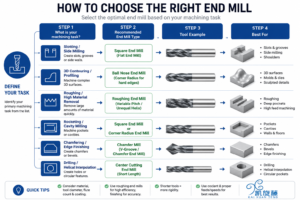
Types of end mills and the geometry they produce
The end profile controls the shape left at the bottom and sides of the cut. A flat surface, a radiused corner and a freeform contour require different tools. Substrate and coating become relevant only after the required geometry has been established.[1]
| End mill type | Machining role | Primary selection risk |
|---|---|---|
| Square end mill | Slots, shoulders, profiles and flat surface machining | High stress at the sharp corner |
| Corner-radius end mill | Roughing, semi-finishing and profiling with an allowed floor radius | Mismatch between the programmed and actual corner radius |
| Ball-nose end mill | Mold surfaces, dies and other 3D contours | Changing effective diameter across the ball profile |
| Roughing end mill | High-volume stock removal with serrated cutting edges | A remaining surface that normally requires finishing |
| Tapered end mill | Drafted walls, mold ribs and deep features | Incorrect taper, tip diameter or CAM reference point |
| Chamfer end mill | Bevels, edge breaks, countersinks and V-grooves | An unsuitable included angle or tip form |
| Center-cutting end mill | Ramping, helical entry and approved axial entry | Restricted chip flow during a straight plunge |
End profile establishes the part geometry. Diameter, flute length, reach, flute count and edge preparation then determine whether the cutter can perform the operation reliably.
Square, corner-radius and ball-nose profiles
A square end mill produces a flat bottom and a near-90-degree floor-to-wall transition. This makes it a common choice for slots and shoulders. The corner carries a concentrated load, however, so runout, interrupted engagement and long overhang can shorten tool life.
A corner-radius tool places more carbide behind the outer corner. That support can improve edge security during roughing and semi-finishing when the specified part geometry permits a fillet.
Ball-nose end mills, or ball end mills, follow curved and freeform surfaces. Their effective cutting diameter depends on where the workpiece contacts the ball. Near the tool axis, the local cutting speed becomes very low; tool orientation and contact position therefore affect finish and wear during 3D machining.[4]
Center-cutting geometry and axial entry
A center-cutting end mill carries an end cutting edge to, or across, the tool axis. This feature permits axial engagement. It does not remove the limitations at the center of the cutter, where low local speed and confined chips make straight plunging demanding. Ramping or helical interpolation is normally preferred when the tool supplier approves those entry methods.[5]
Terminology used in search and purchasing. Phrases such as end mill bits, milling bits and milling machine cutters appear in search data. Industrial catalogs more often use end mill, solid carbide end mill and end milling cutter. A face mill is intended mainly for broad face-milling passes, whereas an end mill is commonly applied to slots, pockets, shoulders and contours.
Selection of carbide end mills and high speed steel end mills
Carbide end mills are widely used on modern CNC machines because the substrate is stiff, wear resistant and able to retain hardness at elevated cutting temperature. Those characteristics are valuable in small diameters, precision finishing, hardened materials and production cycles that depend on stable tool life. Carbide is less forgiving of shock, excessive runout and weak workholding.
High speed steel end mills provide greater toughness and lower brittleness. They continue to serve repair work, moderate cutting speeds and machines that cannot fully exploit carbide. HSS can also be appropriate when interrupted contact or impact presents a greater risk than cycle time. The economic comparison should include tool life, change time, scrap exposure and machine utilization rather than purchase price alone.[6]
| Selection point | Solid carbide | High-speed steel |
|---|---|---|
| Cutting speed | Suited to higher cutting speed in a rigid CNC setup | Normally applied at lower speed |
| Stiffness | Supports accuracy and small tool diameters | Lower stiffness with greater toughness |
| Shock and vibration | Requires good runout control and stable workholding | More tolerant in some interrupted or unstable cuts |
| Typical use | Production milling, hard milling and precision finishing | Maintenance, repair and lower-speed milling applications |
Browse KXT’s solid carbide end mill families by cutter profile, workpiece hardness, flute count and application.
Dimensions that control access, rigidity and chip flow
Several dimensions on an end mill drawing describe different parts of the tool. Treating them as interchangeable can lead to interference, excess overhang or inadequate cutting length.
Flute count as a balance between chip space and edge engagement
The number of flutes changes three conditions at once: available chip volume, the number of edge engagements per revolution and the size of the remaining core. Material group provides a starting point, but radial engagement, depth of cut and evacuation method complete the decision.
| Flute count | Useful characteristic | Condition to monitor |
|---|---|---|
| 1–3 flutes | Large valleys for bulky chips and full-width engagement | Fewer cutting edges and possible loss of core area |
| 4 flutes | A general balance for many steel-milling operations | Chip packing during deep or full-width cutting |
| 5 or more flutes | More edge contacts in finishing and low-radial-engagement toolpaths | Reduced flute volume and increased feed demand |
At a fixed spindle speed and feed per tooth, table feed increases as more flutes are added:
Feed rate = feed per tooth × number of flutes × spindle speed
If the programmed feed cannot be maintained, actual chip thickness falls. The edge may then slide across the material instead of forming the intended chip.
Helix, pitch, rake and edge preparation
A higher helix produces a more gradual entry of the cutting edge and often assists chip lifting and wall finish. It also increases the axial component of cutting force. Reducing the helix angle usually increases edge support and shifts less force in the axial direction.[2]
Variable helix and variable pitch alter the interval between tooth impacts. They may reduce chatter sensitivity, but they cannot compensate for poor clamping, holder runout or unnecessary overhang.[3]
Rake geometry cannot be evaluated separately from the edge hone or chamfer. A sharp positive edge reduces cutting force, while a hone or chamfer strengthens the edge for hard or abrasive work. The expected wear mechanism should guide that choice.
A practical sequence for CNC end mill selection
1. Establish the feature requirements
Record the smallest internal radius, slot width, floor shape, wall shape, draft angle, feature depth and nearby obstructions. From this information, select the end profile and the largest diameter that can enter the feature. Confirm the reach and any need for center cutting separately.
2. Minimize unsupported tool length
Match the flute length to the axial engagement and keep holder-to-cut overhang as short as the part permits. Additional tool length may improve access to a future job, but it reduces rigidity in the present one.
3. Reserve enough flute volume for the chip
A full slot occupies more of the cutter circumference than a light side-milling pass. Deep pockets also require a clear route for air, coolant and chips. On small-diameter tools, a small amount of recutting can overload the edge because the available flute volume is already limited.
4. Specify the workpiece accurately
A material family such as “steel” is too broad for final tool selection. Free-machining low-carbon steel rewards low cutting force and a keen edge. Hardened D2 needs stronger edge support, while Inconel 718 places greater emphasis on heat control and notch-wear resistance. Include the exact grade, condition and hardness in the application data.
5. Set one primary production target
Removal rate, predictable tool life, dimensional stability, unattended machining and low cost per part do not always lead to the same geometry. Define the primary target before comparing tool series.
Coating follows geometry. A coating can improve wear resistance or thermal behavior, but it cannot provide missing clearance, restore rigidity or create chip space in a packed slot.
Material-based starting points
The following table is a screening reference. Final cutting tool selection still depends on cutter diameter, radial engagement, axial depth of cut, holder condition, runout, coolant delivery and the limits of the CNC machine.
| Workpiece group | Geometry to examine first | Dominant process risk |
|---|---|---|
| Aluminum and long-chipping non-ferrous alloys | Two or three flutes, open polished valleys and a sharp cutting edge | Chip packing, built-up edge and recutting |
| Carbon and alloy steels | Four or five flutes with variable pitch when stability requires it | Chatter, heat and corner chipping |
| Stainless steel | Positive geometry, controlled edge preparation and sufficient chip space | Work hardening, built-up edge, heat and notching |
| Cast irons | Rigid, wear-resistant geometry matched to the chip form | Abrasive wear and edge chipping |
| Titanium and nickel-based alloys | Strong core, supported corner and alloy-specific cutting geometry | Concentrated heat, notch wear and sudden failure |
| Hardened tool steels | Short, rigid multi-flute carbide end mill with supported edges | Microchipping, deflection and thermal damage |
Performance criteria for high performance end mills
High performance end mills are application-specific tools. The label has meaning only when the substrate, core, flute count, helix, pitch, edge preparation and coating are connected to a defined material and toolpath.
Performance should be verified with measured production results:
- cycle time and material removal rate;
- tool life and the location of cutting-edge wear;
- surface finish and dimensional consistency;
- chatter, spindle load and process stability;
- parts produced per tool and total cost per part;
- repeatability during automated or unattended machining.
KXT’s documented machining cases and wear measurements identify the workpiece material, machine setup and cutting parameters used in each test. This gives the reader a defined basis for comparing the reported result.
Application examples
Full-width slot in 6061-T6 aluminum
Slot width limits the cutter diameter, and slot depth establishes the minimum flute length. Because the entire diameter is engaged, evacuation capacity becomes critical. A two- or three-flute square end mill with open, polished flutes normally offers a more suitable chip path than a multi-flute finisher designed for steel.
Long-reach finishing in 17-4PH stainless steel
The cutting length should cover the engaged zone, while a reduced neck supplies only the clearance required by the feature. Light radial engagement can support additional flutes, and variable pitch may improve stability. Those advantages depend on adequate table feed and reliable chip removal.
Selection errors that reduce tool life
- Overall length is treated as usable reach. Interference can occur at the neck or shank even when the nominal tool length appears sufficient.
- Flute length is increased without an application need. Unused cutting length reduces stiffness.
- Flute count is increased without checking chip volume. Additional edges also increase feed demand and reduce chip space.
- Coating is selected before cutter geometry. No coating compensates for mechanical interference, trapped chips or an unnecessarily flexible setup.
- The workpiece is described only as steel. The required edge strength and coating depend on the alloy grade, heat-treatment condition and hardness.
- Axial capability is mistaken for drilling capability. A center-cutting end mill still requires an entry method that controls chip flow.
- Cutting data is transferred from an unrelated tool. Initial parameters should come from data for the same tool series, diameter, engagement pattern and machine condition.
Application data for a cutting tool manufacturer
A technical recommendation should be based on enough information to reconstruct the operation. When contacting an end mill supplier or comparing cutting tool manufacturers, provide:
- workpiece grade, condition and hardness;
- operation and CAM toolpath;
- radial width of cut (
ae/RDOC); - axial depth of cut (
ap/ADOC); - required reach and planned overhang;
- machine model and spindle interface;
- holder and measured runout, when available;
- coolant, air blast, MQL or dry-cutting method;
- current tool model and cutting data;
- observed failure mode;
- target finish, tolerance or cycle time;
- monthly tool usage or production volume.
Applications outside the available standard dimensions or geometry can be evaluated through KXT’s custom solid carbide cutting tool service.
Technical clarifications
End mill bits and milling bits
End mill bits is a common search phrase for end mills. Milling bits is broader and can include router cutters, engraving tools and other milling cutters. Purchasing specifications should identify the exact cutter type and intended operation.
Four-flute end mills in aluminum
A four-flute cutter can perform well in a light radial finishing pass when chip evacuation is controlled. Deep, full-width slotting usually benefits from the larger flute valleys available in a two- or three-flute aluminum design.
Flute count and surface finish
Additional flutes can increase the number of edge contacts and support a higher table feed. They do not correct runout, chatter, wall flexibility or poor chip removal. Surface finish is the result of the complete machining system.
Difference between flute length and reach
Flute length covers the axial portion with peripheral cutting edges. Reach extends to the point where a larger neck or shank would interfere with the part. A reduced-neck tool may therefore provide more reach than cutting length.
General-purpose CNC end mill selection
A general-purpose CNC end mill can cover several materials and operations. A tool designed around the actual feature, engagement and workpiece condition will normally produce a more repeatable process.
Controlled qualification of the selected tool
Run the comparison with one workpiece material, holder, toolpath, coolant method and acceptance criterion. Document the cycle time, finished surface, dimensional outcome, service life and observed failure pattern. The resulting record ties the decision to repeatable machining evidence.
Data package for a controlled trial
Document the material grade and hardness, operation, ae, ap, reach, machine, holder, current tool, cutting parameters and observed problem.
KXT’s machining test records provide comparison data, while the custom cutting tool service covers non-standard geometry and reach requirements.
Sources and further reading
- Harvey Performance Company, The Anatomy of an End Mill.
- Harvey Performance Company, Benefits and Drawbacks of High and Low Helix Angles.
- Sandvik Coromant, Milling Cutter Pitches.
- Harvey Performance Company, Ball Nose Milling Strategy Guide.
- Harvey Performance Company, Most Common Methods of Tool Entry.
- Kennametal, Beginner’s Guide to End Mills.
- Brother Industries, End Mill Characteristics and Selection.
- MSC Industrial Supply, End Mills Buying Guide.