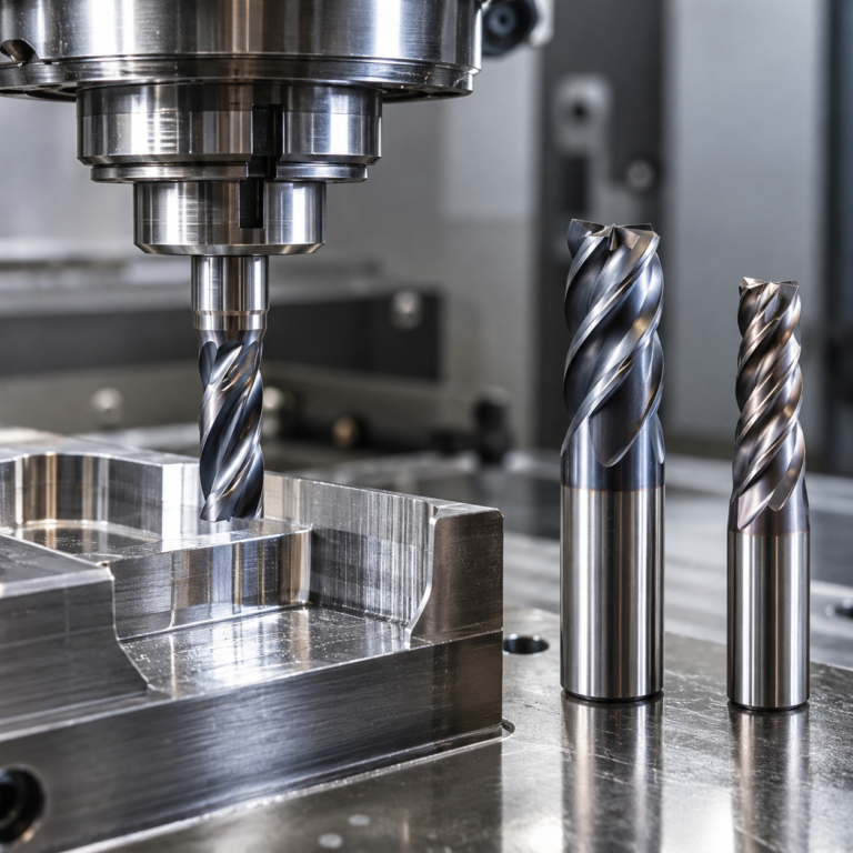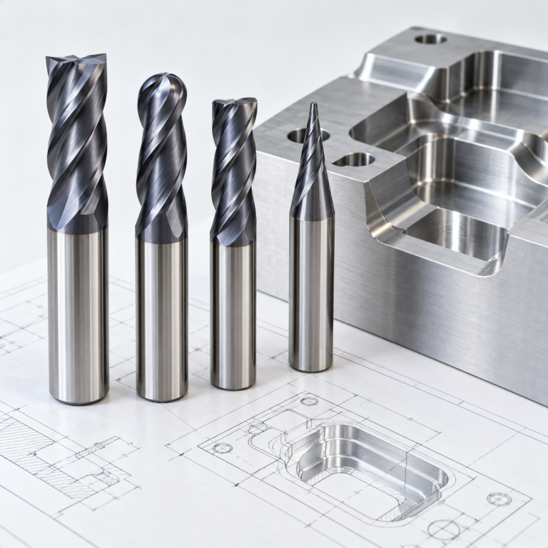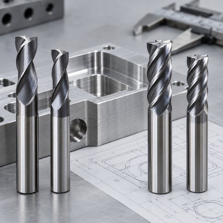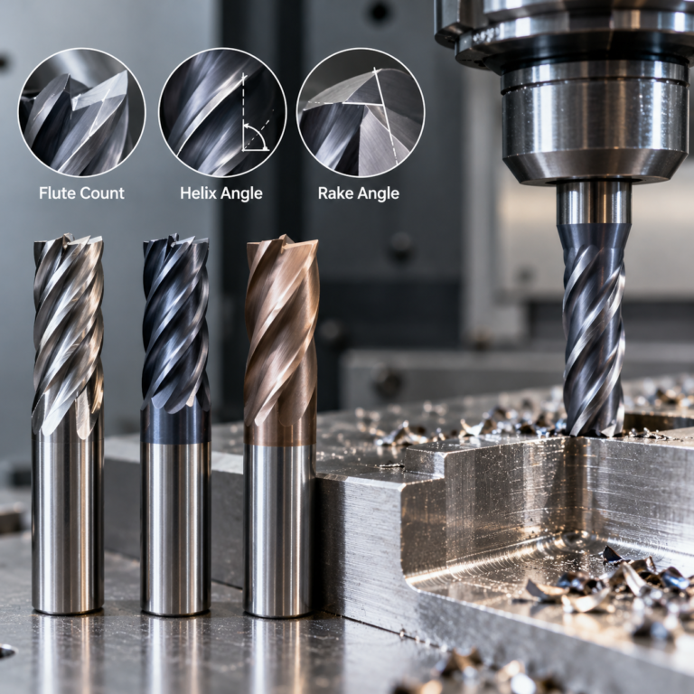
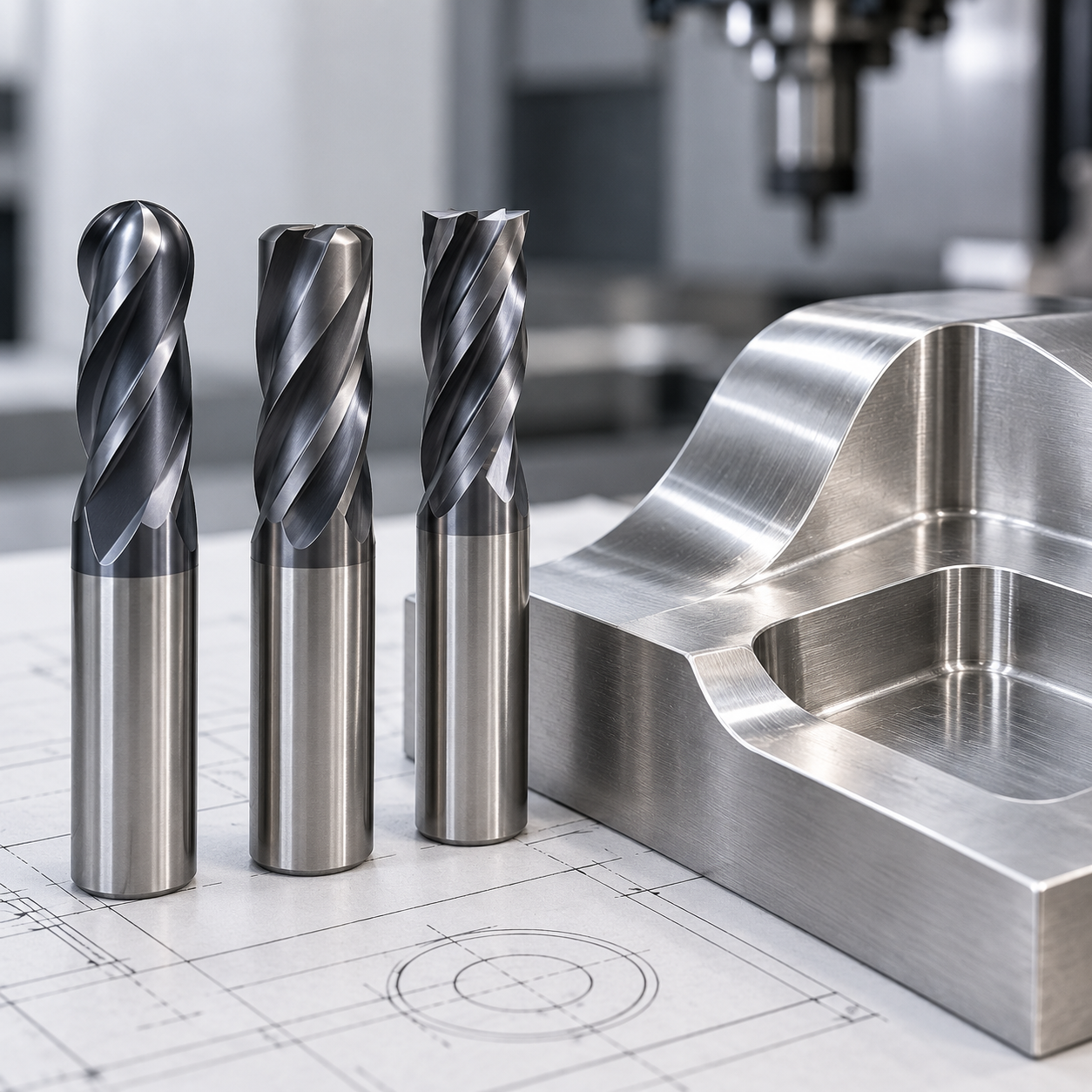
Ball Nose vs Bull Nose (Corner Radius) End Mill: Which to Choose?
Ball nose, bull nose and corner radius are often confused in end mill selection. Ball nose describes a hemispherical tip, while bull nose and corner radius normally refer to a flat-ended cutter with rounded outside corners. An incorrect choice can cause poor surface finish, unsuitable floor-to-wall transitions, or a CAM toolpath that leaves unwanted stock or removes too much material. This guide explains how the three terms relate, works through the geometry and the calculations that drive the decision, and shows how to choose correctly for molds, 3D contours, flat floors and internal fillets.
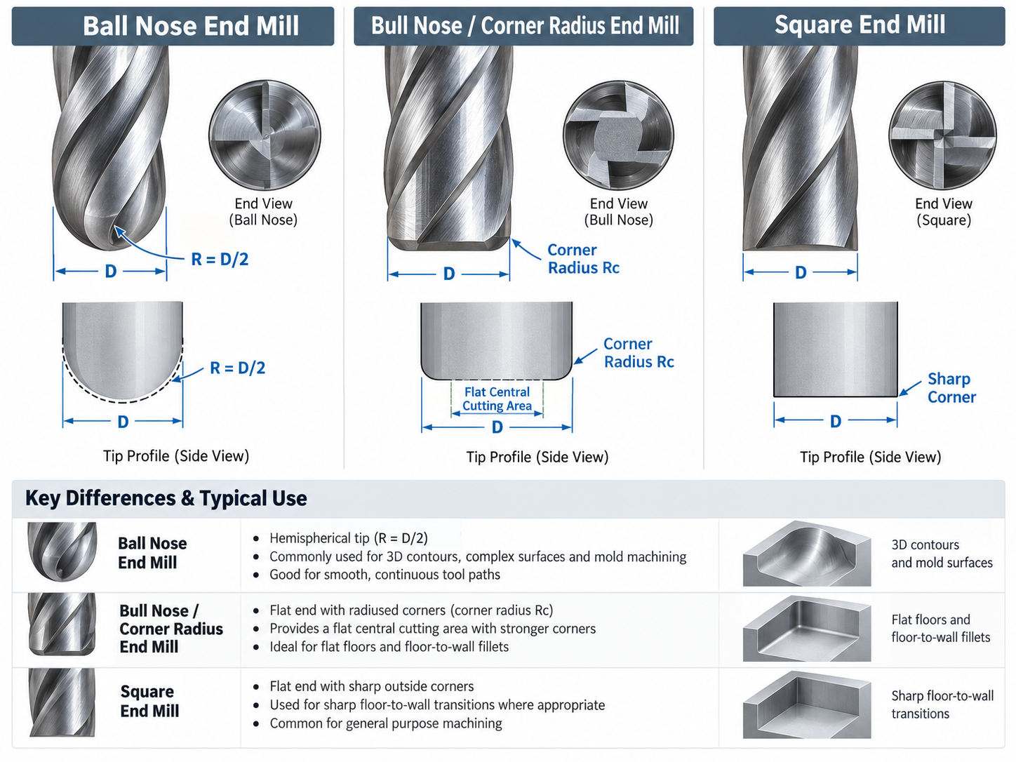
Ball Nose vs Corner Radius (Bull Nose) End Mill: Quick Comparison
Quick answer: choose a ball nose end mill when a hemispherical profile is needed to follow freeform 3D surfaces, mold cavities and sculptured contours. Choose a bull nose (corner radius) end mill for flat floors, shoulders, pocket walls and operations where the specified floor-to-wall radius allows a radiused cutter. The correct choice depends on the part drawing and CAM toolpath, not on tool strength alone.
| Comparison point | Ball nose end mill | Bull nose (corner radius) end mill |
|---|---|---|
| Tip profile | Full hemisphere | Flat bottom with a radius at each corner |
| Tip radius | R = D/2, center on the tool axis | Rc smaller than D/2, at the outer corner |
| Flat floor | Can approximate a flat floor with overlapping passes; scallops remain | Flat floor can be machined with the central flat portion |
| Best work | Freeform 3D contours and mold finishing | Pockets, shoulders and radiused floor-to-wall transitions |
| Edge strength | No sharp square outer corner; geometry affects edge support | Radius replaces the fragile sharp square corner |
| Key programming point | Effective diameter varies with depth | Define as a flat tool with the exact corner radius |
| Main weakness | Very low cutting speed near tool-axis center | Produces a corner fillet; cannot generate a smaller-than-tool fillet |
Is a Bull Nose End Mill the Same as a Corner Radius End Mill?
In many industrial catalogs, yes — "bull nose" and "corner radius" describe the same basic profile: a flat cutting end with a radius ground between the bottom and side cutting edges. Some manufacturers reserve "bull nose" for a larger, more noticeable radius and use "corner radius" for small values, but there is no universal dividing dimension. The supplier drawing and specified corner radius define the tool more precisely than the name alone.
The four terms that must be kept separate:
| Term | Geometry | What it machines |
|---|---|---|
| Ball nose end mill | Hemispherical tip, R = D/2 | Freeform 3D and curved surfaces |
| Bull nose end mill | Flat end with an outer corner radius | Flat floors and pockets with permitted floor-to-wall fillets |
| Corner radius end mill | Generally the same tool as bull nose; check the supplier's spec | Generally the same as bull nose; verify specification |
| Corner rounding end mill | Form tool with an edge-rounding profile, sometimes with a pilot | Rounds an exposed workpiece edge |
The corner rounding tool is the important trap. It does not cut a flat-bottomed pocket or an internal fillet; it is a forming-style cutter used to round an exposed edge of the part, and front and back variants exist depending on which face the radius sits on. Treating a corner rounding tool as a corner radius tool is a common purchasing error.
Cutting Geometry: Ball Radius vs Corner Radius
The geometry reduces to where the radius sits and how large it is.
Ball radius
A ball nose tip is a hemisphere whose center lies
on the tool axis, so the ball radius is always half
the nominal diameter: R = D/2.
There is no flat central area. When the tool follows
a curved surface, the contact point moves along the ball
and the local cutting diameter changes with it.
Corner radius
A bull nose tool keeps a flat central area and places a smaller radius Rc at each outer corner. Corner radii are offered in many sizes, from small edge-protection radii to larger bull-nose profiles. There is no single radius-to-diameter ratio that defines all corner-radius end mills. The radius replaces the sharp 90-degree square corner, which is the weakest point of a square end mill, with supported carbide. The part drawing must allow the resulting fillet. A cutter with a corner radius larger than the specified concave floor-to-wall fillet cannot generate that smaller fillet directly.
Which Is Better for 3D Contour Milling?
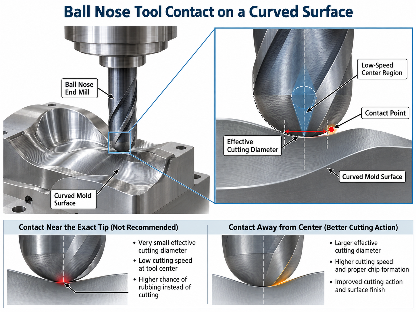
For many freeform surfaces — including mold cavities, die surfaces and sculptured contours — a ball nose end mill is a common choice. Its hemispherical tip can machine varied surface orientations using appropriate raster, Z-level, flowline or other finishing toolpaths. Tool contact, clearance and remaining stock must still be checked.
Two conditions govern how well it works. First, the tip itself has near-zero surface speed at the tool axis, so a ball nose cutting dead center rubs rather than shears. Where machine kinematics and part accessibility permit, tool tilt can move the contact away from the center; the appropriate angle depends on the tool, local surface normal and collision clearance. On 3-axis machines, use the toolpath and cutting parameters to manage the low-speed center region.
Second, the cutter must fit the local concave geometry without gouging, and the shank and holder must clear surrounding features.
A properly modeled bull nose can also be used on selected 3D surfaces, especially when larger regions are relatively shallow or when a flat or corner-radiused profile matches the feature. It is not automatically unsuitable for all freeform machining; local curvature, accessibility and toolpath compensation determine whether it fits.
Which Is Better for Flat Floors and Internal Fillets?
Where the part has a flat floor and permits a floor-to-wall fillet, a bull nose end mill is often an efficient option. The flat central portion helps machine the floor while the radiused outer edge forms the floor-to-wall transition. Check that the corner radius, tool diameter and programmed allowance match the drawing.
A ball nose can approximate a flat floor using closely spaced passes, but its spherical profile tends to leave scallops between passes. A flat-ended tool is generally a more direct choice when an efficient, flat-bottom finish is required. Whether subsequent finishing is needed depends on the specified tolerance and surface requirement.
If the drawing requires a sharp floor-to-wall corner, a square end mill is generally more appropriate than a bull nose or ball nose. Separately, a sharp internal corner in the XY plane cannot be produced by a cylindrical end mill of finite diameter; its internal corner radius is limited by the cutter radius and tool accessibility. The required feature radii, wall geometry and access limits must therefore be checked separately before choosing cutter diameter and corner radius.
Roughing vs Semi-Finishing vs Finishing
| Stage | Preferred tool | Reason |
|---|---|---|
| Roughing | Bull nose, or a dedicated roughing end mill | A radiused cutting corner can improve edge support in suitable cuts |
| Semi-finishing | Ball nose for contours; bull nose for walls and floors | Leaves controlled stock allowance for the finishing operation |
| Finishing | Ball nose on curved surfaces; bull nose on flat floors and shoulders | Toolpath and stepovers are set for the target geometry and finish |
For suitable roughing and semi-finishing operations, a corner radius may strengthen the edge compared with a sharp square corner. Ball nose tools are then often selected for curved finishing. Actual tool life depends on cutter geometry, coating, workpiece hardness and cutting conditions.
Surface Finish, Scallop Height and Stepover
On a planar surface, adjacent parallel ball-nose passes can leave small ridges called scallops or cusps. For an ideal spherical cutter of radius R, parallel passes on a flat surface with tool axis perpendicular to the plane, and a stepover s no greater than the ball diameter, the geometric scallop height is:
For small stepovers this simplifies to the commonly used approximation:
Worked example with R = 5 mm (a 10 mm ball nose):
| Stepover s | Exact h | Approximation s²/(8R) |
|---|---|---|
| 0.5 mm | 0.0063 mm | 0.0063 mm |
| 1.0 mm | 0.0251 mm | 0.0250 mm |
For small stepovers, doubling s increases the theoretical scallop height by approximately four times. This geometric height is not the same as measured roughness Ra. On inclined or curved surfaces, the contact geometry changes; use the CAM scallop-height or surface-quality functions and verify actual results by measurement.
Effective Cutting Diameter and Cutting Speed
When a ball nose engages a horizontal plane to an axial depth ap measured from the lowest point of the ball, the cutting circle is smaller than the nominal diameter if 0 < ap < D/2. In this simplified, untilted geometry, the effective diameter is:
Illustrative calculation: a 10 mm ball nose at ap = 1 mm
gives De = 2√(10 × 1 − 1) = 6 mm.
If 120 m/min were an appropriate cutting speed for the
particular material and cutter, the illustrative RPM
based on that contact diameter would be:
At 3,820 RPM, the peripheral speed of a 6 mm contact circle would be approximately 72 m/min, rather than 120 m/min. This does not mean higher RPM is always safe or necessary: use the toolmaker's limits, available machine speed, tooth load and the actual contact condition.
For tilted ball-nose paths or complex 3D surfaces, this simple formula does not capture the full contact geometry; rely on appropriate CAM and cutting-data methods. Do not apply the ball-nose equation directly to a bull-nose profile without accounting for its different geometry.
CAM Toolpath and Programming Considerations
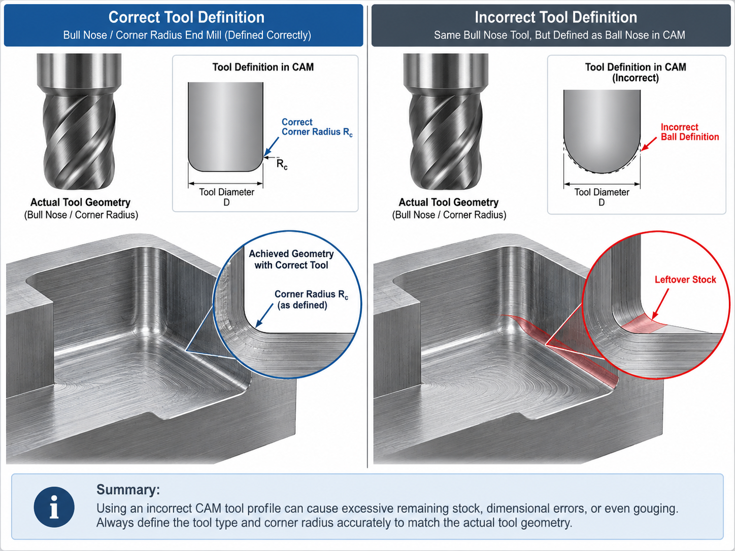
- Define the tool correctly: a ball nose is entered as a full ball; a bull nose is entered as a flat tool with the exact corner radius. Defining a bull nose as a ball changes the calculated contact and can gouge the floor or leave stock along the corner.
- Match the radius to the measured tool: ground radii vary slightly from nominal; use the measured Rc so the simulated and real surfaces agree.
- Check collisions on the holder and shank: deep cavities and tilted cuts need holder collision checking, not just flute checking.
- Manage rest material: use rest machining to clear stock left by a larger tool, especially in internal corners where engagement spikes.
- Watch corner engagement: a stable wall pass can overload when it enters an internal corner; constant-engagement or trochoidal strategies smooth the spike.
- Choose the toolpath to the surface: raster for broad surfaces, Z-level for steep walls, and flowline or dedicated finishing paths for tight sculptured geometry.
Practical Tool Selection Examples
Example 1 — Curved injection-mold cavity
A suitable roughing tool removes bulk stock; a ball nose can then semi-finish or finish the sculptured cavity. Select the ball diameter and tool reach from the local surface curvature, remaining allowance and collision clearance.
Example 2 — Flat-bottom pocket with a 3 mm fillet
If the drawing permits a 3 mm floor-to-wall fillet, a bull nose with Rc = 3 mm may be considered for floor and wall machining, provided the cutter diameter, access and remaining stock are suitable. A ball nose could machine the floor with multiple passes but usually less directly.
Example 3 — Hard milling a die at 55 HRC
A short, rigid corner-radius cutter with a carbide grade and coating qualified for the workpiece may be evaluated for roughing or semi-finishing. A suitable ball nose may then finish the curved die surfaces. Cutting parameters and tool life require validation.
Example 4 — Five-axis aerospace blade
Where machine access permits, a tilted ball nose may keep the contact away from the tool-axis center. Tilt direction and angle must be selected from the blade geometry and verified for holder clearance, surface finish and cutting load.
Example 5 — Aluminum freeform fixture in 6061
A ball nose with suitable sharp cutting geometry can be considered for curved aluminum faces. Confirm chip evacuation, spindle speed, feed and toolpath using the selected tool's data; flute count alone does not determine performance.
Common Mistakes When Choosing Ball and Bull Nose Tools
Common mistakes
- Defining a bull nose as a ball in CAM. The simulated contact no longer matches the real tool and the floor can be gouged or left with excess stock.
- Expecting efficient flat-floor machining from a ball nose. It can approximate a flat floor, but close stepovers and geometric scallops may increase the cycle time.
- Ignoring effective diameter. The contact circle may be smaller in shallow, untilted ball-nose cuts; use the correct engagement model and toolmaker recommendations.
- Ignoring the low-speed ball center. Where accessible, orientation and toolpath strategy can move contact away from the tool axis.
- Ignoring the print's fillet radius. A cutter with Rc larger than the required concave floor-to-wall radius cannot generate that smaller fillet directly.
- Confusing corner rounding with corner radius. A corner-rounding form tool is intended for exposed edge radii, not as a general substitute for a bull-nose cutter.
- Using too large a stepover. Scallop height grows with the square of stepover and can exceed the finish requirement.
- Neglecting overhang and runout. Neither profile compensates for a flexible or eccentric setup.
Pre-programming selection checklist
- Verify the surface: freeform contour, planar floor, wall or floor-to-wall fillet.
- Record cutting diameter D, ball radius R or corner radius Rc and the required feature radii.
- Confirm minimum tool access, usable reach, cutting length and holder clearance.
- Define the real cutter profile in CAM; inspect gouging, collisions and remaining stock.
- Set stepovers and cutting data from the specified finish and actual cutter recommendations.
Frequently Asked Questions
What is the difference between a ball nose and a bull nose end mill?
A ball nose has a full hemispherical tip with R = D/2 and follows 3D curved surfaces. A bull nose keeps a flat bottom with a smaller radius at each corner and is used for flat floors, pockets and shoulders where the fillet is permitted.
Is a bull nose the same as a corner radius end mill?
In most manufacturers' usage, yes: the two names describe a flat end with a radius at the corner. Some suppliers use "bull nose" for larger radii, so always check the drawing and the measured radius rather than relying on the name.
What does a corner rounding end mill do?
It is a form cutter for rounding an exposed workpiece edge. It differs from the flat-ended corner-radius or bull-nose end mill used for general profiling and certain floor-to-wall fillets.
Can a ball nose end mill machine a flat floor?
Yes, it can approximate a flat floor through overlapping passes, but the spherical tip leaves geometric scallops. A suitable square or corner-radius end mill is generally a more direct choice for a flat-bottom feature, subject to the required floor-to-wall radius.
How is scallop height calculated?
For adjacent parallel ball-nose passes on an ideal flat plane, h = R − √(R² − s²/4), or approximately h ≈ s²/(8R) for small stepovers. This geometric cusp height is not the same as measured Ra.
What is effective cutting diameter?
For an untilted ball nose contacting a horizontal plane at a depth ap measured from its lowest point, the contact-circle diameter is De = 2√(D × ap − ap²). Tool tilt and curved surfaces change the contact geometry, so do not use the simplified formula for every 3D toolpath.
Which tool is better for hardened mold steel?
Choose from the feature and cutter design rather than hardness alone. A qualified corner-radius tool may be useful for roughing or semi-finishing, while a ball nose is often selected for sculptured surface finishing. Confirm carbide grade, coating, rigidity and cutting conditions.
Why is the ball nose radius always half the diameter?
The tip is a hemisphere centered on the tool axis, so its radius equals the nominal tool radius by definition. A corner radius tool is not a hemisphere, which is why its Rc is smaller and a flat central area remains.
Technical References
- Harvey Performance — The Anatomy of an End Mill . Tool profile, corner radius, ball nose and cutter geometry.
- Harvey Performance — Ball Nose Milling Strategy Guide . Contact position, effective diameter and tool orientation.
- KXT — Types of End Mills . Tool profiles and selection principles for CNC milling.
Calculations and case scenarios in this article illustrate general tool-selection principles. They are not controlled KXT production tests or universal cutting parameters.