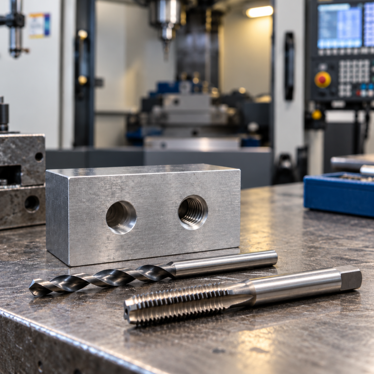

1/4-20 Tap Drill Size: #7 Drill (0.2010 in / 5.1054 mm)
Need the right drill bit for a 1/4-20 tap? Start with the tap type. A conventional cutting tap and a chipless thread-forming (roll) tap require different hole sizes—even though both produce a 1/4-20 UNC internal thread. This guide gives the standard cutting-tap size, verified inch-to-metric conversions, nearby drill alternatives, and practical checks for machine-shop production.
Quick answer · 1/4-20 UNC cutting tap
Use a #7 drill bit (0.2010 in / 5.1054 mm) as the conventional starting size for tapping a 1/4-20 UNC internal thread with a cutting tap.
The nominal thread diameter is 0.2500 in (6.350 mm), with 20 threads per inch (TPI). Always confirm the drill recommendation against the specific tap manufacturer's specifications and the thread requirements on the drawing.
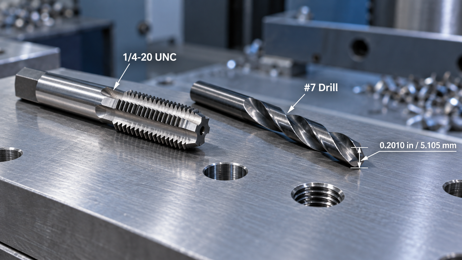
Important: The #7 recommendation applies to conventional cutting taps, not automatically to form taps, thread milling, or 1/4-inch pipe threads.
What Does 1/4-20 UNC Mean?
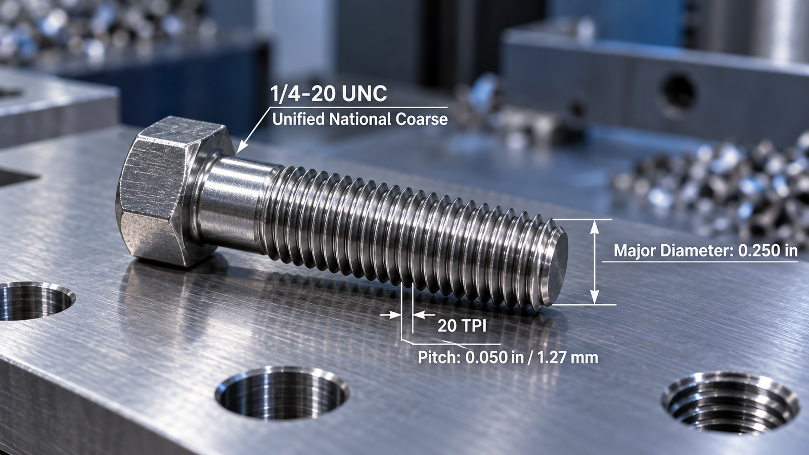
1/4-20 UNC identifies a Unified National Coarse inch-series screw thread. The 1/4 indicates the nominal major diameter in inches; 20 means 20 threads per inch; and UNC designates the coarse-pitch series of the Unified Thread Standard (UTS).
| Property | Inch Value | Metric Equivalent |
|---|---|---|
| Nominal major diameter | 0.2500 in | 6.350 mm |
| Threads per inch | 20 TPI | — |
| Thread pitch | 0.0500 in/revolution | 1.270 mm/revolution |
| Conventional cutting-tap drill | #7 · 0.2010 in | 5.1054 mm |
Thread pitch is the axial spacing between corresponding points on adjacent threads. The nominal major diameter is not the hole size to drill before tapping: the tap needs material in the hole wall to generate the internal thread profile.
Do not confuse 1/4-20 UNC with 1/4-28 UNF (a fine-pitch machine screw thread) or 1/4-18 NPT (a tapered pipe thread). These are distinct thread forms with different tooling and hole requirements.
1/4-20 Tap Drill Size Chart: #7 and Nearby Options
A #7 drill measures exactly 0.2010 in by nominal drill size. In metric units, that is 5.1054 mm—often rounded to 5.11 mm on shop charts. A 5.1 mm drill is very close, but it is not mathematically identical.
| Drill Size | Diameter (in) | Diameter (mm) | Application Notes |
|---|---|---|---|
| #7 | 0.2010 | 5.1054 | Conventional starting point for a cutting tap. |
| 5.1 mm | 0.2008 | 5.1000 | Very close metric size; verify the hole produced and applicable tolerance. |
| 13/64 in | 0.2031 | 5.1594 | Slightly larger hole; use only if permitted by the tap and thread requirements. |
| #6 | 0.2040 | 5.1816 | Larger than #7; not an automatic substitute. |
Decimals shown to four places in the inch column. For 13/64 in, the exact value is 0.203125 in = 5.159375 mm. These are nominal drill diameters, not guarantees of the finished hole size.
Can a 13/64-Inch Drill Replace a #7?
Sometimes, but it is not a universal replacement. A 13/64-in drill is 0.002125 in (0.053975 mm) larger than a #7. A larger drilled hole leaves less material for the tap and can change the finished minor diameter and thread height. For a noncritical job, the result may still meet the specified thread requirements, but production parts must be checked against the drawing and tap supplier's recommended hole range.
Do not choose a smaller drill simply to obtain a tighter fit. Thread fit depends on the completed thread geometry and specified tolerance class, not just the pilot-hole diameter.
How Does 1/4-20 Compare With 1/4-28?
| Thread | Series | TPI | Common Cutting-Tap Drill |
|---|---|---|---|
| 1/4-20 | UNC · Coarse | 20 | #7 · 0.2010 in (5.1054 mm) |
| 1/4-28 | UNF · Fine | 28 | #3 · 0.2130 in (5.4102 mm) |
The fine-thread tap uses a different pitch and a different starting hole size. Always identify the complete thread designation—not merely the 1/4-in nominal diameter.
Cutting Tap vs. Form Tap: Why the Drill Size Changes
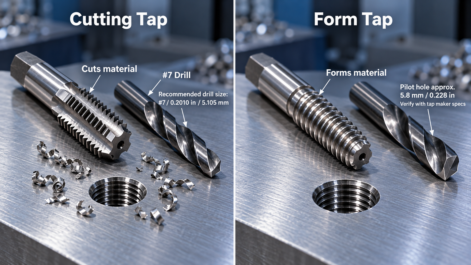
This is the most important distinction in choosing a 1/4-20 tap drill. A cutting tap removes material to create internal threads and produces chips. A form tap (also called a roll tap) displaces suitable ductile workpiece material to produce the thread without conventional cutting chips.
| Selection Point | Cutting Tap | Thread-Forming / Roll Tap |
|---|---|---|
| How threads are made | Material is cut away. | Material is plastically displaced. |
| Conventional 1/4-20 starting hole | #7 · 0.2010 in | Manufacturer-specific. Haas lists 5.8 mm; a Guhring 1/4-20 form-tap series specifies 0.225–0.228 in. |
| Chip formation | Produces chips that must be managed. | Does not generate normal cutting chips. |
| Application considerations | Appropriate tap geometry and cutting conditions for the workpiece. | Requires suitable material ductility, lubrication and closely controlled hole size. |
Do not interchange these starting-hole dimensions. The Haas Tooling roll-tap chart lists 5.8 mm for 1/4-20 as a starting recommendation and cautions that material, hardness and tolerance may require adjustment. Guhring's 1/4-20 form-tap series 3959 specifies a 0.225–0.228 in drill range. These recommendations are tool-specific; they should not be treated as interchangeable universal values.
Form tapping can be attractive in suitable ductile materials because it eliminates conventional tapping chips. It is not automatically suitable for every alloy or hardness condition. Follow the exact form-tap manufacturer's hole preparation, lubricant and application instructions.
How to Estimate a Cutting-Tap Drill Size
A familiar shop-floor rule of thumb for conventional cutting taps is to subtract the thread pitch from the nominal major diameter. It provides a first-pass estimate, not a dimensional acceptance standard or an exact formula for thread percentage.
Quick estimate for an inch-series cutting tap
Approximate drill diameter =
Major diameter − (1 ÷ TPI)
0.2500 − (1 ÷ 20) =
0.2500 − 0.0500 = 0.2000 in
The commonly selected nearby standard drill for 1/4-20 UNC is #7, 0.2010 in.
The estimate helps explain the nominal size, but it does not account for all factors affecting final thread geometry, percentage of thread, tolerance class, material behavior or actual hole size. For production, use the tap manufacturer's chart and the part drawing rather than choosing a drill from the rule of thumb alone.
Choosing the Hole Size for Steel, Stainless Steel and Aluminum
The correct starting diameter depends first on the thread specification and tap type. Workpiece material then affects cutting torque, lubrication, tool life and the actual hole quality. Avoid blanket rules such as "always drill smaller in aluminum" or "always drill larger in stainless."
| Material Group | Practical Concern | What to Verify |
|---|---|---|
| Carbon and alloy steel | Chip evacuation, torque and tool wear. | Tap grade, hole size, coolant/lubrication and thread inspection. |
| Stainless steel | Work hardening, adhesion and high tapping loads in many grades. | Grade-specific tap geometry, appropriate lubrication and actual hole diameter. |
| Aluminum alloys | Built-up edge, material adhesion and thread deformation. | Lubrication, chip clearance, thread class and suitability for form tapping. |
| Cast iron and other brittle materials | Abrasive wear and material-dependent chip behavior. | Tap design and material suitability; do not assume form tapping is appropriate. |
For a specified internal thread class such as 2B or 3B, verify the finished thread using the drawing's acceptance criteria and appropriate thread gages. Those classes describe requirements for the finished thread; simply changing the drill diameter is not a substitute for controlling thread geometry.
CNC Drilling and Tapping: A Practical Setup Checklist
On a CNC mill, tapping success depends on more than the drill's nominal diameter. Hole location, runout, depth, toolholding, chip control and spindle-feed synchronization all affect the result.

- Verify the thread callout. Confirm 1/4-20 UNC, the required thread class, right- or left-hand direction, minimum full-thread depth and whether the hole is through or blind.
- Identify the tap type. Use the cutting-tap or form-tap drill recommendation for the actual tool in the setup, including any manufacturer-specified hole range.
- Drill a controlled hole. Select the drill for the workpiece and machine rigidity. Check runout, tool condition and the hole diameter produced—not only the drill shank marking.
- Plan chip evacuation and bottom clearance. Spiral-point taps commonly direct chips forward and are often used for through holes. Spiral-flute taps commonly help evacuate chips from blind holes. Verify the tool's specific application and the clearance needed for its chamfer and chips.
- Check tapping synchronization. In rigid tapping, axial feed must match the actual pitch and spindle rotation. Confirm the correct feed mode and canned-cycle behavior for the specific CNC controller.
- Inspect the finished thread. Verify the required full thread depth, burr condition, thread quality and GO/NO-GO gage acceptance where specified.
What Feed Rate Matches a 1/4-20 Tap?
For synchronous tapping, a 1/4-20 thread advances 0.0500 in per spindle revolution (1.270 mm per revolution). If the programmed spindle speed is 500 rpm, the matching axial feed is:
Feed (in/min) = RPM ÷ TPI =
500 ÷ 20 = 25.0 in/min
Equivalent feed =
500 × 1.270 = 635 mm/min
This is a mathematical feed example, not a recommended tapping speed. The permissible rpm depends on the workpiece, tap, coating, holder, lubrication and machine. CNC controls also differ in how they interpret feed-per-minute, feed-per-revolution and tapping cycles; consult the machine and control documentation before programming.
Through Holes vs. Blind Holes
A through hole provides an exit path for chips and the tap. A blind hole has a bottom, so the drill-point depth, tap chamfer length, chip space and specified full thread depth all matter. The drilled depth generally must exceed the required full-thread depth, but the amount is application- and tool-dependent. Confirm the setup rather than using a single universal extra-depth value.
Why 1/4-20 Taps Break or Fail Thread Inspection
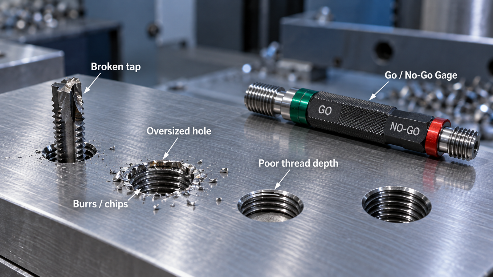
When a tapped hole fails, inspect the full process before changing the nominal drill size. These checks help distinguish a drilling problem from a tapping or inspection problem.
| Observed Issue | Possible Causes | First Checks |
|---|---|---|
| Tap breaks or torque rises sharply | Undersized hole, packed chips, unsuitable tap, misalignment or poor lubrication. | Measure the hole, inspect chip flow and check toolholding and cutting conditions. |
| GO gage does not enter | Pitch-diameter error, damaged thread, incomplete depth, burrs or an incorrect tap. | Check thread callout, full-thread depth, tap condition and gaging procedure. |
| NO-GO gage enters beyond the permitted limit | Oversize or incorrect thread geometry, tool or process variation. | Verify the gage, thread tolerance, tap specification and measured thread geometry. |
| Inconsistent results between holes | Drill runout, tool wear, varying material or unstable coolant/chip removal. | Measure multiple drilled holes and monitor tool condition and setup repeatability. |
For critical threaded joints, use the specified inspection method and documented acceptance limits. A screw that happens to fit by hand is not sufficient evidence that the completed thread meets its dimensional requirements.
Frequently Asked Questions About 1/4-20 Tap Drill Size
What size drill bit do I need for a 1/4-20 tap?
For a standard 1/4-20 UNC cutting tap, the conventional reference is a #7 drill, 0.2010 in (5.1054 mm). Confirm the selected cutting tap's drill-range recommendation.
What is the metric equivalent of a #7 drill bit?
Exactly 5.1054 mm. A 5.1 mm drill is a close metric alternative, not an exact conversion.
Can I use 13/64 inch instead of a #7 drill?
A 13/64-in drill is slightly larger at 0.203125 in. It may be acceptable in some applications if the resulting thread meets the drawing and the tap supplier's limits, but do not assume that it can always replace #7.
Is the drill size the same for a 1/4-20 roll tap?
No. A 1/4-20 form or roll tap needs a larger, manufacturer-specified starting hole than a conventional cutting tap. For example, Haas lists 5.8 mm, while a Guhring form-tap series lists 0.225–0.228 in.
Does a 1/4-28 tap use the same drill as a 1/4-20 tap?
No. Common cutting-tap chart values are #7 (0.2010 in) for 1/4-20 UNC and #3 (0.2130 in) for 1/4-28 UNF.
Is a 1/4 NPT tap the same as a 1/4-20 tap?
No. A common 1/4-18 NPT pipe thread is a tapered sealing-thread system; 1/4-20 UNC is a straight machine screw thread. Use the correct pipe-thread drill and tapping instructions when NPT is specified.
How can I confirm that a tapped hole is correct?
Check the specified thread series, tolerance class, usable thread depth and the finished thread with the required inspection method. GO/NO-GO thread plug gages are commonly used for internal threads, with acceptance criteria determined by the applicable specification.
Final Recommendation
For most readers asking "what drill size for a 1/4-20 tap?", the useful starting answer is a #7 drill (0.2010 in / 5.1054 mm) for a conventional 1/4-20 UNC cutting tap. The finished hole must still meet the selected tap's guidance and the engineering drawing.
If you are using a thread-forming tap, do not use the #7 cutting-tap recommendation. Check the manufacturer's larger starting-hole specification, material suitability and lubrication requirements. For repeatable CNC production, confirm actual drilled diameter, tap alignment, chip control, tapping synchronization and finished-thread inspection.
Technical Sources and Verification Notes
Reference values were checked against manufacturer documentation and established shop drill-size conventions. Source-specific values are identified above so they are not mistaken for universal process settings.
- Guhring — 1/4-20 Pionex Cutting Tap, Series 391 . Manufacturer cutting-tap product specifications.
- Guhring — 1/4-20 UNC Form Tap, Series 3959 . Form-tap-specific nominal drill range (0.225–0.228 in).
- Haas Tooling — Roll Tap Drill Size Chart (PDF) . 1/4-20 roll-tap example: 5.8 mm; includes process and tolerance cautions.
- OSG USA — Technical Charts and Tap Drill References . Additional manufacturer literature for tap drill size and pitch-limit selection.
Technical reference reviewed October 26, 2026. Dimensional values are reference starting points; individual tap specifications, part drawings, applicable threading standards and actual process measurements govern production acceptance.